DLP-523: Detailed Level Procedure 363-206-285
Page 27 of 30 Issue 2, February 2000
DDM-2000 OC-3 MULTIPLEXER
BBF6 T1EXT
51. Determine circuit pack option switch settings from office records, work order,
or old circuit pack settings.
52. Set T1EXT option switches per Table N and Figure 8.
53.
NOTE:
If a signal has previously been applied to the original T1EXT circuit pack,
the FAULT LED may flash when the new T1EXT is installed until the
signal tests good.
Remove old T1EXT and install replacement T1EXT.
Response: FAULT LED on the T1EXT flashes for about 40 seconds
and then goes off.
54. STOP. YOU HAVE COMPLETED THIS PROCEDURE.
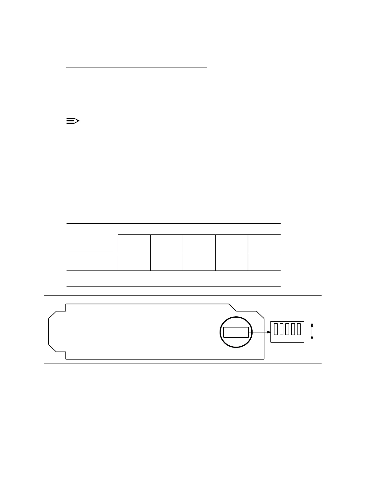
Figure 8 – BBF6 T1EXT Option Settings
TableN–T1LineCodeSettings
Line Code
Format
Switch S1 Settings
S1-1
(Port 1)
S1-2
(Port 2)
S1-3
(Unused)
S1-4
(Unused)
S1-5
(Unused)
B8ZSOFFOFF
OFF OFF OFF
AMI ON ON
Note: Switch 1, section 3 (S1-3), section 4 (S1-4), and section 5 (S1-5) are
unused and must be set to OFF.
Connector
Edge
5
Component Side
S1
OFF
ON
4321