363-206-285 Detailed Level Procedure: DLP-523
Issue 2, February 2000 Page 28 of 30
DDM-2000 OC-3 MULTIPLEXER
BBF9/BBF10 IMA LAN
55.
NOTE:
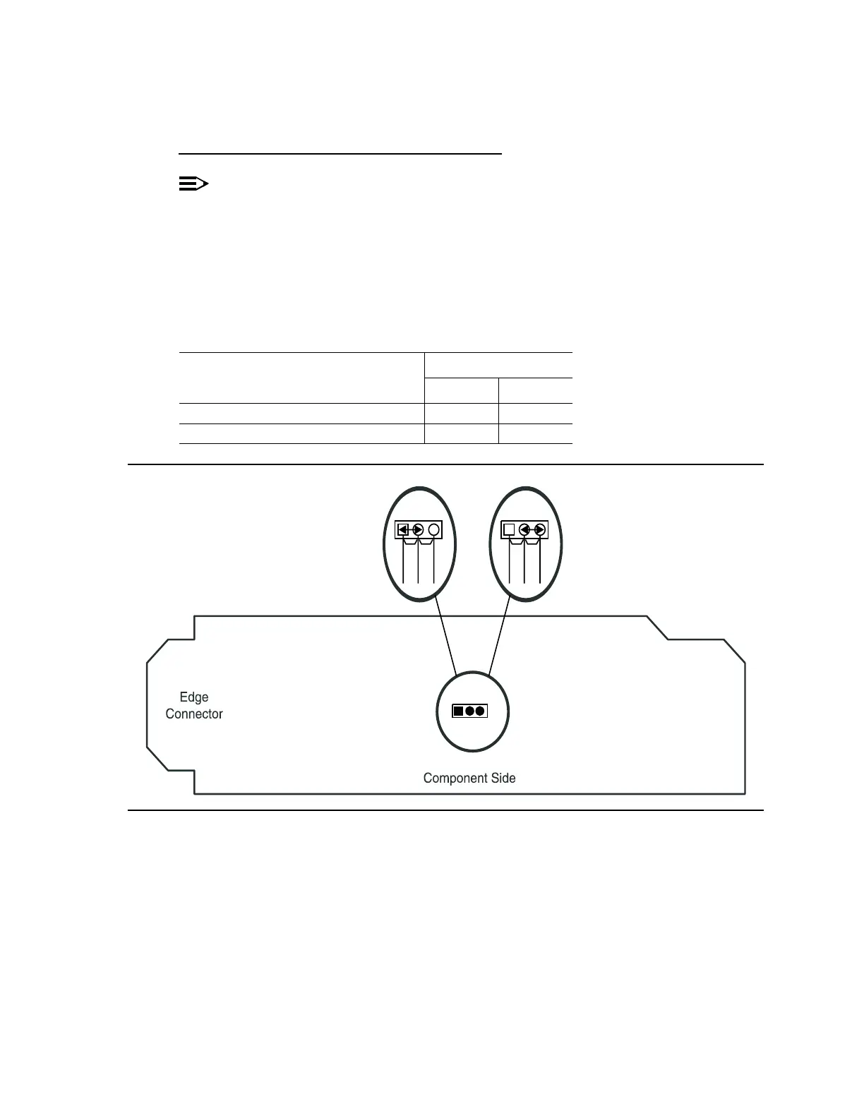
The only hardware option settings on IMA LAN circuit packs are the
power settings (located on the bottom circuit board) shown in Figure 9. If
there are other jumpers on the circuit pack similar to the power jumpers,
they are factory test points and should be ignored.
Refer to Table O and Figure 9 and set power jumpers.
Figure 9 – IMA LAN Power Settings
Table O – IMA LAN Power Settings
Corresponding FUNCTION UNITS IMA Power Setting
MXRVO Circuit Pack +5 V –48 V
BBG2 MXRVO X
BBG2B MXRVO X
-48V
-48V
-48V+5V
+5V
+5V