M A E D A Mini-Crawler Crane Section 4 – OUTRIGGER SETTING
3/2019 MC305C-3 4-39
• Crane operation should proceed with
respect to the values specified in "MID.
OUTRIGGER POSITION" in the rated total
load chart.
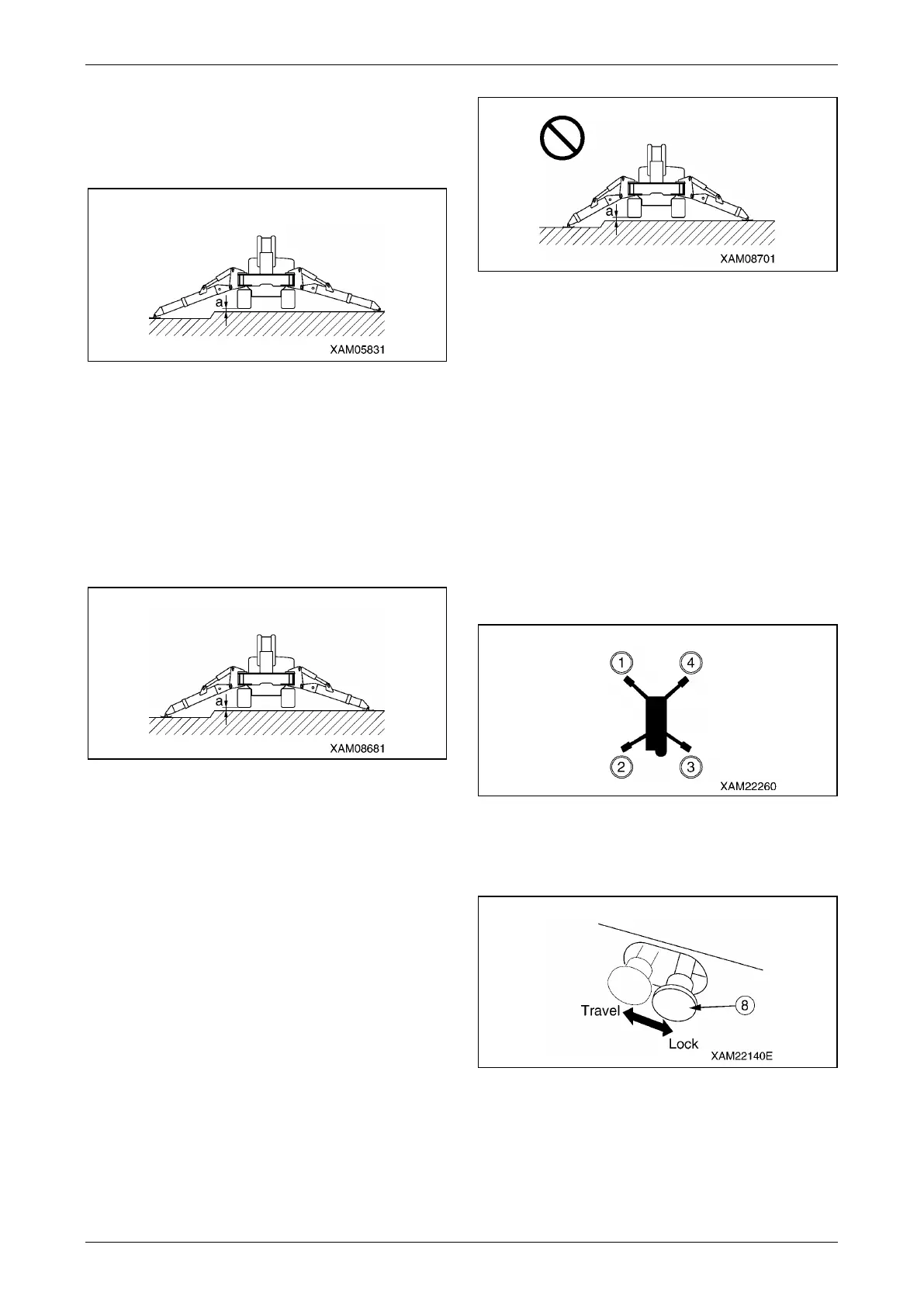
Fig. 4-88
• Despite the medium extension of all the
outriggers, the width of extended outriggers
decreases due to an ungraded ground even
when clearance "a" in the figure is 50 mm.
Crane operation should proceed with
respect to the values specified in "MIN.
OUTRIGGER POSITION" in the rated total
load chart.
Fig. 4-89
• Crane operation with the outriggers
extended at the minimum is permitted only if
the outriggers are placed on a level surface.
50 mm of dimension between the outrigger
bottom and crawler bottom should be
obtained.
• On ungraded ground or similar, the width of
extended outriggers decreases even when
clearance "a" in the figure is 50 mm. Do not
perform crane operation under such
extension condition. Potential overturning of
the machine may occur that leads to serious
personal injury if disregarded.
Fig. 4-90
• The machine becomes unsteady at some
point if it undergoes a 360-degree slewing
with an object hoisted. Irrespective of the
rated total load, ensure operation in a short
working radius and at low speed.
58B57BTasks to Be Performed upon
Engine Stop
There are four outriggers installed to the machine.
Although the setting method is described for just
one outrigger (outrigger (4)), set the other three
outriggers in the same way.
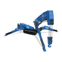
Fig. 4-91
1. Operate the travelling lock lever (8) to the
"LOCK" position.
Fig. 4-92