ELECTRIC SYSTEM 16000 SERVICE/MAINTENANCE MANUAL
3-4
Published 05-03-17, Control # 228-03
TEST VOLTAGES
The Model 16000 operating system uses the EPIC
®
system
with CAN Bus
®
technology. The CAN Bus system uses
multiple nodes containing controllers that communicate with
the node 1 (master) controller by sending data packets over
a two-wire bus line. The data packets are tagged with
addresses that identify the system components of each
node.
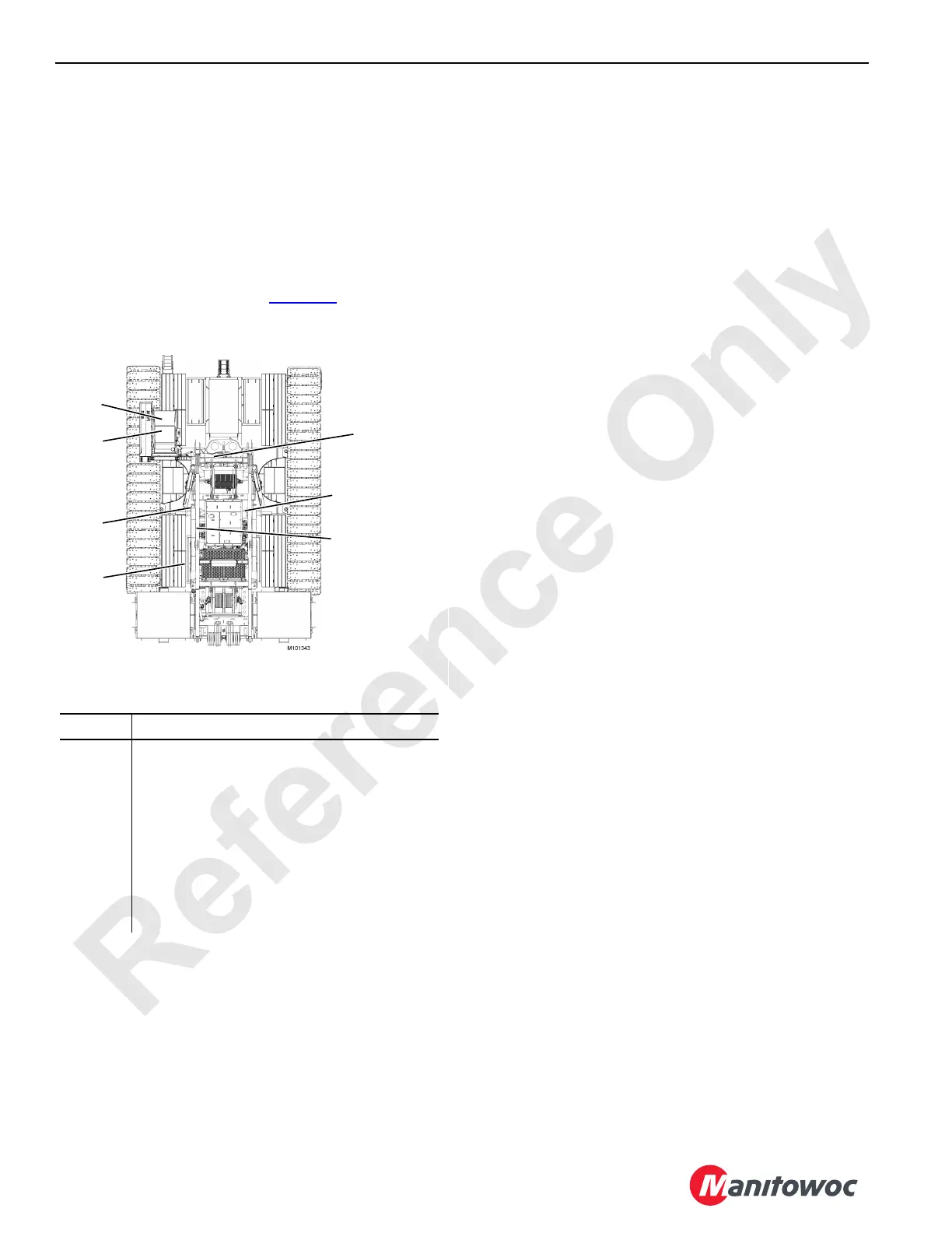
This section contains test voltages sorted by the nodes. The
nodes are listed and identified in Figure 3-3
.
Node Table Heading Descriptions
The CAN tables on the following pages provide information
found on the crane’s electrical schematics at the end of this
section.
Interpret the connector codes using the following example
for code 34-R:
• The number 34 is the cable number:
- The number 3 is the node number.
- The number 4 is the receptacle number where the
item is located on the node.
• The last character R is the receptacle pin number.
The Function Type indicates the type of connection, such as
power, ground, signal, analog input (AI), digital input (DI), or
digital output (DO).
The Receptacle/Pin No. (Engine Node-0 only) indicates the
input-to-receptacle number and pin number code.
The Wire No. (Engine Node-0 only) indicates the wire-to-
computer receptacle or wire number code.
The CAN Packet Number indicates the location of items for
all nodes except node 0, which does not have CAN packet
numbers. For example, interpret CAN Packet Number
CAN129-3-4 (Drum 1 Park Switch) using the following:
• CAN129 is the packet location number.
• Number 3 is the bank where information is stored.
• Number 4 is the identifier for that item.
Node Description
1 Master (Front Console)
2 Handles and Cab Controls
3 Drum Pump, Alarms, Sensors, and Accessories
4 Pressure Senders, Drum 4, and Accessories
5 Drum 2, Sensors, and Auto Lubrication
6 Drum Brakes, Pawls, and Sensors
7MAX-ER
0 Engine
FIGURE 3-3
1
2
3
4
5
0
In Boom Butt
(without MAX-ER)
7
On MAX-ER
Front Rotating Bed
(with MAX-ER)
6
 Loading...


