Manitowoc Published 05-03-17, Control # 228-03 1-41
16000 SERVICE/MAINTENANCE MANUAL INTRODUCTION
The control handle is inoperable when the drum 3 park brake
is applied.
The hydraulic charge pressure from the system charge
pump supplies the hydraulic make-up fluid to the low-
pressure side of the motor. A pressure sender in the high-
pressure side of the pump leg provides system pressure
information to the Node-1 controller. The low-side pressure
supplies hydraulic pilot pressure to operate the motor
servos. A fixed orifice between pump ports A and B allows
for smoother drum operation.
When the load drum 3 motors rotate, a speed sensor at
motor rotor monitors and sends an input voltage to the Node-
1 controller. The Node-2 controller sends an output voltage
to the rotation indicator in the control handle. As the drum
rotates faster, the rotation indicator on top of the control
handle pulsates with a varying frequency that indicates the
drum rotational speed. The handle command in percent from
neutral is shown on the Diagnostic Screen.
The continuous changing of the closed-loop fluid occurs with
the leakage in the pump, the motor, and the external
sequence/flow valve. The sequence/flow valve opens at 14
bar (203 psi) and removes 15 Lpm (4 gpm) of hot fluid from
the system by discharging the exhausted fluid into the motor
case where the fluid returns to the tank.
Load Drum 3 Brake and Pawl
The hydraulic pressure to operate the drum 3 brake is from
the low-pressure side of the system. The hydraulic pressure
to operate the drum pawl is from the low pressure accessory
system.
When the drum 3 brake switch is in the ON-park position, the
drum brake release solenoid HS-25 is disabled so the brake
is applied to the drum shaft. The drum 3 pawl in the solenoid
HS-26 is enabled to keep the pawl applied to the drum
flange. The drum pump does not stroke in response to
control handle movement.
When the drum 3 brake switch is placed in the OFF-park
position, the brake release solenoid HS-25 remains applied.
The brakes remain applied until the Node-6 controller sends
a 24 volt output to release the brake. The Node-6 controller
sends a zero volt output signal to the drum pawl in the
solenoid HS-26 and a 24 volt output to enable the pawl out
solenoid HS-27 to release the pawl. The drum circuit is
active, waiting for a control handle command.
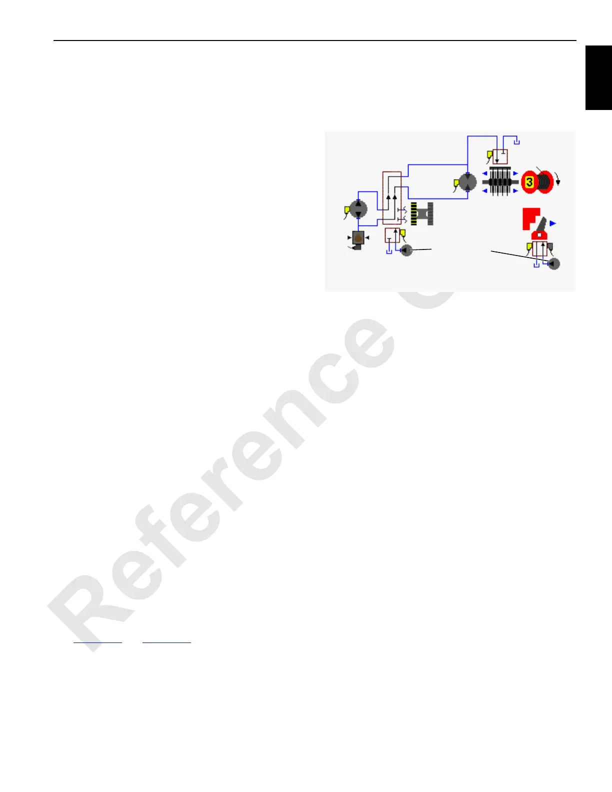
Raising
See Figure 1-26 and Figure 1-28.
When the drum 3 control handle is moved back for raising,
an input voltage of 2.6 volts or more is sent to the Node-1
controller. The Node-4 controller sends a 24 volt output to
enable the left travel to the drum 3 diverting solenoid HS-28.
The Node-3 controller sends a variable 0 to 24 volt output
that is divided by a resistor and applied to the pump 2 EDC in
the raising direction. The Node-6 controller sends a variable
0 to 24 volt output that is divided by a resistor and applied to
the motor PCP. The Node-1 controller checks that the drum
block-up limit switches are closed and no system faults are
present.
The Pump EDC tilts the swashplate in the raising direction
to satisfy the pressure memory. The Node-1 controller
compares the drum holding pressure to the value in the
pressure memory. When the system pressure is high
enough, the Node-6 controller sends a 24 volt output to
enable the drum 3 brake release solenoid HS-25. The drum
brake solenoid shifts to block the drain port and opens the
port to the low-pressure side of drum system to release the
brake from the drum shaft.
The pump EDC tilts the swashplate in the raising direction
as the hydraulic fluid flow is from the pump port to the motor
port. Return fluid is from the motor outlet port to the pump
inlet port.
The Node-3 controller output voltage to the pump EDC and
the Node-6 controller output voltage to the motor PCP is
relative to the control handle movement. As the control
handle is moved back, an output voltage increases the pump
swashplate angle.
When the system pressure exceeds the PCOR (Pressure
Compensating Over-Ride) valve setting of 340 bar (4,931
psi), the valve shifts to direct flow from the shuttle valve into
the maximum displacement side of the servo cylinder. The
PCOR valve over-rides the command from the servo PC
valve, increasing the motor displacement and the output
torque while reducing the output speed. When the PCOR
valve closes, the control of the motor returns to the servo PC
valve.
The Node controllers continuously balance the drum system
pressures and monitor the motor displacement angle so the
motor displacement goes to the minimum when the control
handle is all the way back, if the motor torque requirement is
not too high. The Node-1 controller monitors the motor
displacement and controls the motor speed by regulating the
hydraulic fluid flow through the pump.
FIGURE 1-26
HS-25
HS-27
HS-28
Brake
Diverting
Valve
Motor
(PCP)
Pump
(EDC)
Pressure
Sender
Pawl
HS-26
16-1021
Accessory Pump
(Low-Pressure)