Manitowoc Published 05-03-17, Control # 228-03 1-15
16000 SERVICE/MAINTENANCE MANUAL INTRODUCTION
operation. If the charge pressure is set too high, the
hydraulic system could be damaged. When a system control
handle is in the neutral position the main display indicates
the system charge pressure.
If any charge pressure system drops, the system brake
begins to apply at approximately 14 bar (203 psi). The main
system pumps de-stroke as charge pressure drops to the
minimum pressure. The accessory pump de-strokes if the
suction side pressure drops below 11 bar (160 psi).
Hydraulic Motors
See the hydraulic motor manufacturer’s service manual for a
complete description of a hydraulic piston motor.
Variable-displacement low torque/high speed, bent axis
piston hydraulic motors are used in the travel, boom/mast
hoist, and load drum systems. The swing system motor is a
fixed displacement, low torque/high speed, bent-axis piston
hydraulic motor. Each motor contains a cylinder block,
pistons, output shaft, and internal flushing valve. The boom/
mast hoist and load drums motor have a Pressure Control
Pilot (PCP) valve that controls the output speed/torque of the
motor.
The motor cylinder block axis is tilted at an angle to the
output shaft with pistons fitted axially around its axis. The
internal end of the output shaft has a large flange face similar
to a pump swashplate. The motor piston ends are connected
to output flange face and do not ride around the axis of the
rotating flange face like the pump pistons.
Hydraulic fluid from the pump enters the selected inlet side of
the motor and places a force against the pistons. The
retained piston ends place a thrust against the output flange
with a rotational torque that turns the output shaft. This also
rotates the cylinder block on the bent axis, while the tilt angle
to the flange face moves the pistons as they rotate. Hydraulic
fluid displaced by the motor pistons exits the motor and
returns to the inlet side of the system pump through the
hydraulic piping.
Pressure Monitoring
The main display indicates the selected system pressures.
The system pressure displayed is the charge pressure or
greater. System pressure can also be checked when the
system is stroked at each pressure sender diagnostic
coupler with a 690 bar (10,008 psi) high pressure gauge.
Basic Operation
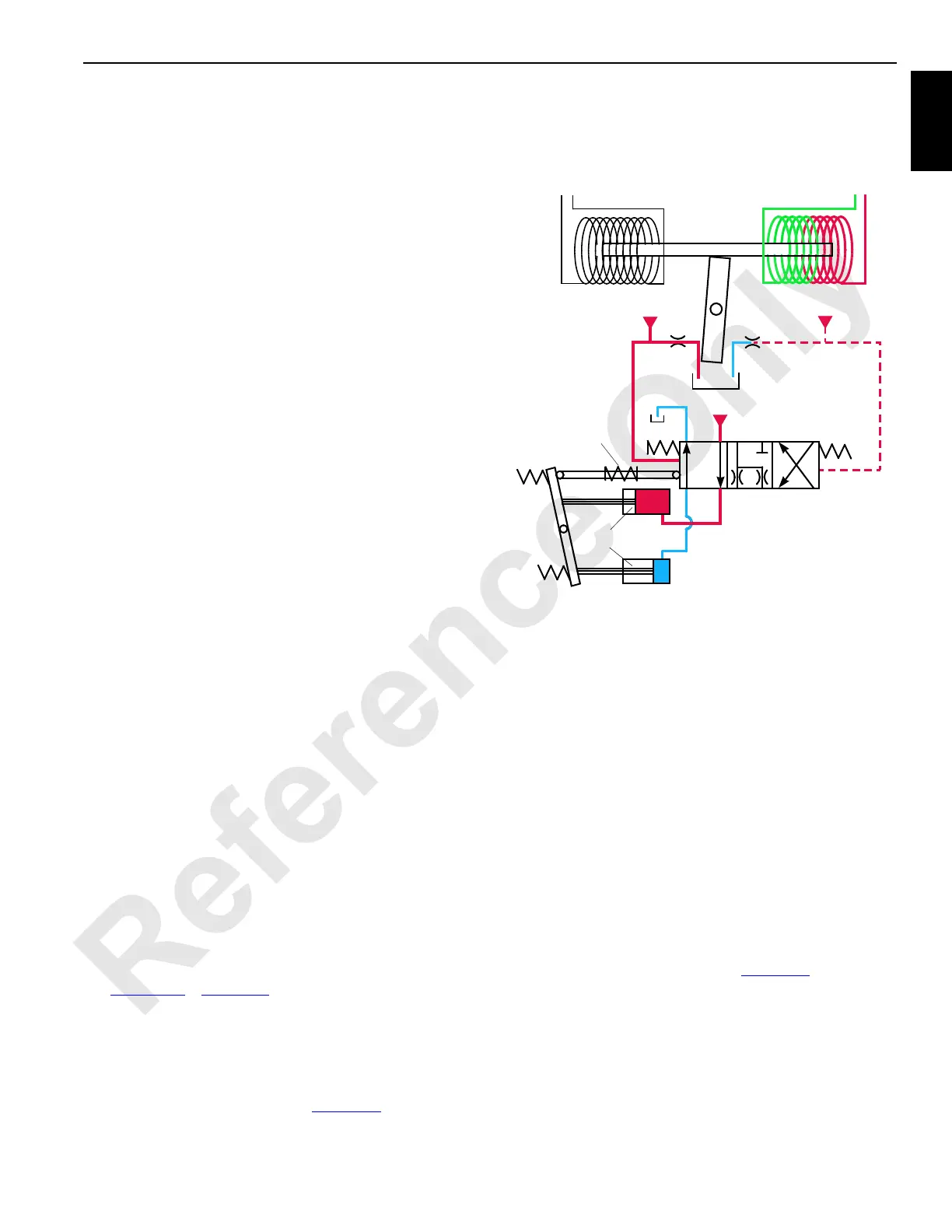
See Figure 1-8 or Figure 1-9 for the following procedure.
When a control handle is moved from the neutral position, an
input voltage in the handle command direction is sent to the
Node-1 controller. The selected component node controller
sends a variable 0 to 24 volt output that is divided by a
resistor and applied to the pump external EDC. The output
current magnetizes an armature (Figure 1-8
) and starts to
block one of the orifice ports, depending on the command
direction.
Blockage of flow at the exhaust side of the right orifice port
causes a pressure difference across the spool. This pressure
difference overcomes the resistance of the spool spring and
moves the spool proportionally to pressurize the top servo
pistons. The fluid from the bottom servo pistons is routed to
the tank. This tilts the swashplate, stroking the pump in the
selected command direction. As the swashplate tilts, the
chamber spring is pulled in the opposite direction of the
spool with the a linkage. This centers and maintains the
spool in a neutral position until the 1 bar (15 psi) chamber
spring pressure is reached.
In travel pumps, the pressure relief and pressure-limiting
sections of multifunction valves respond when the relief
pressure is reached. The pressure-limiting function of travel
pumps is set not to exceed 420 bar (6,092 psi). If the travel
pump pressure exceeds the preset pressure limit, the pumps
de-stroke to prevent overheating of the system fluid.
Hydraulic fluid pressure overcomes the spring resistance in
the pressure-limiting relief valve (1, Figure 1-9
), shifting the
spool to open a line for fluid pressure. The servo check valve
(2) is spring loaded with an opening pressure of 52 bar (754
psi). Hydraulic fluid from the pressure-limiting relief valve
flows through the exhaust port of the displacement control
valve (3).
The exhaust port has a restricted orifice that develops
pressure for the servo control cylinder (4) to pressurize and
FIGURE 1-8
Spool
Pilot Pressure
Control Voltage
From Controller
Pilot Pressure
Pilot Pressure
Orifice
Port
Orifice
Port
Spool
Spring
Swashplate
Servo Pistons
Armature
Modulation
Spring
Control Voltage
From Controller
16-1002