Manitowoc Published 05-03-17, Control # 228-03 2-25
16000 SERVICE/MAINTENANCE MANUAL HYDRAULIC SYSTEM
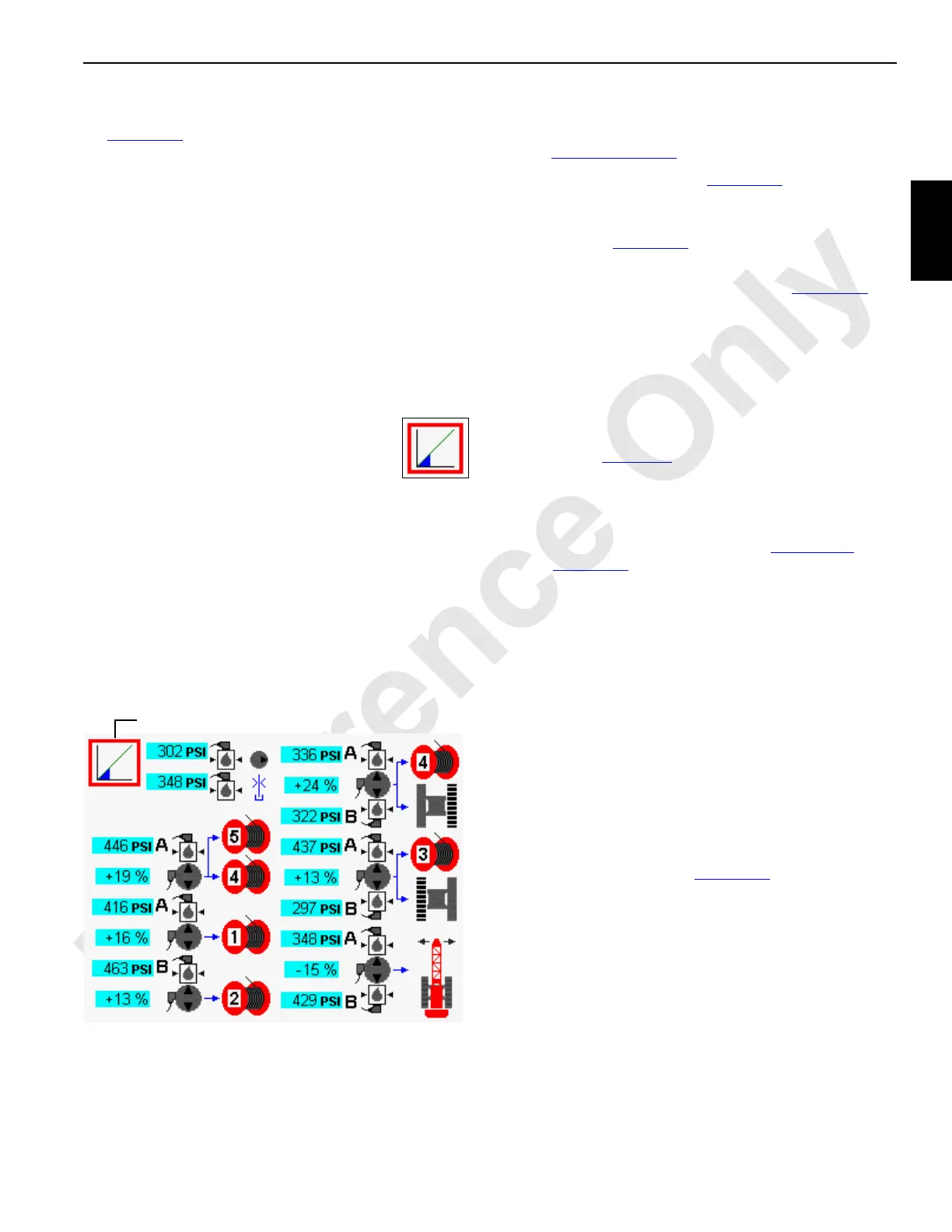
Charge Pressure Test
See Figure 2-22 for the following procedure.
The charge pressure test checks the ability of all primary
crane functions to build proper charge pressure. This test
generally is used only as a shop procedure on new cranes. It
can also be used as a quick way to test hydraulic
components in the primary hydraulic circuits. Charge pump
pressure must be within 19 to 27 bar (276 to 392 psi).
Test charge pressure using the following procedure:
1. Apply all the park brakes with the switches on the control
console.
2. Start and run the engine at low idle.
3. Press the Enter button to go to the Pressure Test and
Calibration screen from the Menu screen.
4. Press the Enter button to go to level 2. Use
the Select buttons to show the LOW
PRESSURE icon in the data box.
5. Press the Confirm button to start the test.
6. The test starts and the percent of completion is
displayed in the data box.
7. When the test is complete, the charge pressure icon
reappears in the data box.
Charge pressure levels must be within a specified range
during this test. Any pump that failed to maintain charge
pressure within a specified range is highlighted in yellow.
Troubleshoot the failed circuit to determine the cause of
fault.
High Pressure Adjustment
The following adjustment is only required when a system
fails the High Pressure Test
.
Unless otherwise specified, see Figure 2-23
for the following
procedure:
1. Scroll to the diagnostic screen for the corresponding
function (see Figure 2-24
).
2. Disconnect the electrical connector from the
corresponding brake solenoid valve (see Figure 2-12
).
3. With the engine running at low idle, slowly move the
desired control handle:
• In either direction from off for swing or travel
• Back from off (hoist direction) for all drums
4. Do not demand any more than 20% handle command.
5. Pressure on the screen should indicate the pressure
specified in Table 2-10
.
6. If the proper pressure is not indicated, adjust the
corresponding multi-function valve:
a. Remove the protective cap (3) from the multi-
function valve (1 or 2). See Table 2-10
and
Figure 2-17
for pump port identification.
b. Loosen the lock nut (4)
DO NOT tamper with the bypass hex (6). See the
pump manufacturer’s instructions.
c. Using an internal hex wrench, adjust the multi-
function valve adjusting screw (5):
- Turn IN to increase the pressure
- Turn OUT to decrease the pressure
7. Repeat step 6 until the specified pressure is indicated.
8. Hold the adjusting screw (5) in position and securely
tighten the lock nut (4).
9. Install the protective cap (3).
10. Reconnect the electrical connector to the corresponding
brake solenoid valve (see Figure 2-12
).
FIGURE 2-22
D16-29B
Data Box
 Loading...


