Manitowoc Published 05-03-17, Control # 228-03 1-63
16000 SERVICE/MAINTENANCE MANUAL INTRODUCTION
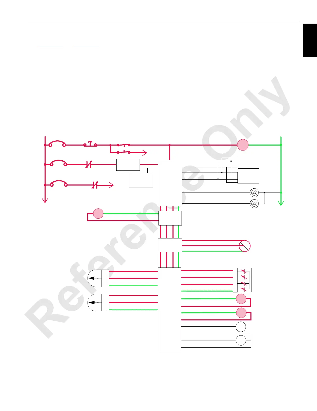
Telescopic Beam Cylinder
See Figure 1-51 and Figure 1-52.
The telescopic beam cylinder connects the wheeled
counterweight assembly to the crane. The beam can be
positioned to three different positions depending on the
crane configuration.
The telescopic beam has a counterbalance valve at each
cylinder port to provide smooth operation when operating.
The counterbalance valves lock the cylinder in position and
also provide relief protection for the cylinder. The telescopic
beam three position spool valves are motor spooled where
both cylinder ports and the tank port of the valve spool
section are connected in the center position.
The top and bottom telescopic beam position encoders
detect telescopic beam position and direction of the beam
movement. The Node-1 controller receives this input
information as two out-of-phase square wave voltages that
are converted to counts. The information screen in the
operator cab indicates the telescopic beam extend position
in inch or metric.
Power is available to hand-held wireless remote control
when, the engine is running, The MAX-ER function mode is
selected, and the power button is pressed. The telescopic
beam cannot be extended/retracted until the electrical
cables and hydraulic lines are connected between the rear of
crane and the telescopic beam of the MAX-ER.
HS
90
HS
91
MAX-ER Base
Level Sensor
+
–
PWR
CAB
System Fault Alarm
RCL Cab Fault Alarm
P11-07
P11-19
Display 1
Display 2
P11-01
P12-31
P12-32
P11-21
Start
WCP
CAN Power
Run 3
P12-24
Cab Power
Engine Stop
10 Amp
50 Amp
24 Volts
50 Amp
6C5A
6C5
CB7
6A
6C7
6C14
CB5
CB8
8C
8
NODE 0
NODE 1
(Master)
76-a
76-E
76-S 24 Volts
AI
Gnd
76-b
AI
73-n
24 Volts
73-b
AI
73-hGnd
Top Telescopic
Beam Position
Sensor
73-s
24 Volts
73-e
AI
73-kGnd
Bottom Telescopic
Beam Position
Sensor
A
B
C
D
2
3
1
2
3
1
Telescopic Beam
Hinge Pin In
76-C
76-B
76-D
76-C
76-G
76-F
76-H
76-G
HS
88
HS
89
Telescopic Beam
Hinge Pin Out
Telescopic Beam
Cylinder Extend
Telescopic Beam
Cylinder Retract
NODE 7
HS
68
34-C
34-D
Accessory System
Proportional Valve
NODE 3
M16-06
Hand-Held
Wireless
Remote
Telescopic Beam
Gnd
DO
Gnd
Gnd
Gnd
Gnd
DO
DO
DO
DO
46-g
Accessory System
Pressure Sensor
46-j
46-h
Hyd
psi
24 Volts
AI
Gnd
2
3
1
NODE 4
FIGURE 1-51