Manitowoc Published 05-03-17, Control # 228-03 7-23
16000 SERVICE/MAINTENANCE MANUAL POWER TRAIN
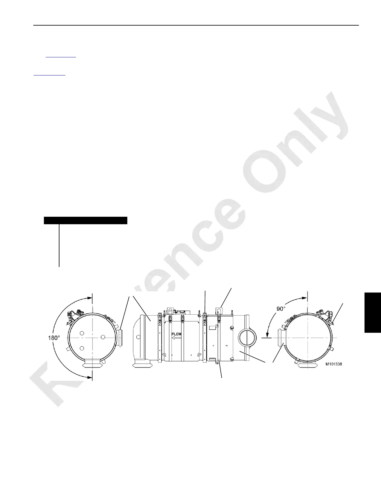
DPF/DOC Module Inlet Re-orientation
See Figure 7-15 for the following procedure.
Re-orient a replacement DPF/DIC if it is not oriented per
Figure 7-15
. If the inlet section (1) cannot be re-oriented,
contact the supplier for a replacement module that has all
components in the proper orientation.
To re-orient the module, use the following procedure:
1. If necessary, remove the thermistor (6) located on the
inlet. Using an appropriate high-temperature sealant,
install a plug into the threaded hole.
2. Orient the inlet section:
a. Loosen the V-band clamp (3) that connects the inlet
section until it can be freely rotated. Do not remove
the clamp or the gasket.
b. Loosen the band clamp (4) that holds the lifting tab
(2) and the clamps for the thermistor wire onto the
inlet section.
c. Rotate the inlet section to the orientation shown.
d. Tighten the V-band clamp to 20 Nm (15 ft-lb).
Gently tap the circumference of the V-band clamp
with a rubber mallet to make sure that the clamp is
properly seated. Re-tighten to 20 Nm (15 ft-lb).
e. Position the lifting tab back to vertical. Position the
band clamp hardware 35° from the tab.
f. Tighten the band clamp to 7.3 Nm (64 in-lb).
3. Reinstall the thermistor using an appropriate high-
temperature sealant.
NOTE: The white-insulated wires must not be within 25
mm (1 in.) of the module body.
Avoid sharp bends and excessive tension in the wires.
FIGURE 7-15
Item Description
1 Inlet Section (DOC)
2 Lifting Tab
3 V-Band Clamp
4 Band Clamp
5 Outlet Section (DPF)
6Thermistor
1
2
3
4
5
6