Manitowoc Published 05-03-17, Control # 228-03 2-27
16000 SERVICE/MAINTENANCE MANUAL HYDRAULIC SYSTEM
Charge Pressure Adjustment
The following adjustment is only required when a system
fails the Charge Pressure Test
.
1. Scroll to the diagnostic screen for the corresponding
function (see Figure 2-24
).
2. Start and the run engine at high idle. With the function in
neutral, the system pressure on the diagnostic screen
should read 22 to 26 bar (319 to 377 psi).
3. If the specified pressure is not indicated, stop the engine
and connect an accurate 0 to 69 bar (0 to 1,001 psi)
hydraulic pressure gauge to the coupler at the
corresponding pressure sender (see Figure 2-30
).
4. Repeat step 2. If the specified pressure is still not
indicated:
• Perform a Pressure Sender Test
. Replace the faulty
pressure sender if needed
• Perform a Control Calibration
If the specified pressure is still not indicated, take the
following actions:
• If pressure is too high, check that the pump neutral
is adjusted properly. If the pressure is still high,
adjust the charge pressure relief valve.
• If pressure is too high, adjust the charge pressure
relief valve. If you cannot raise the charge pressure,
excessive system leakage is indicated.
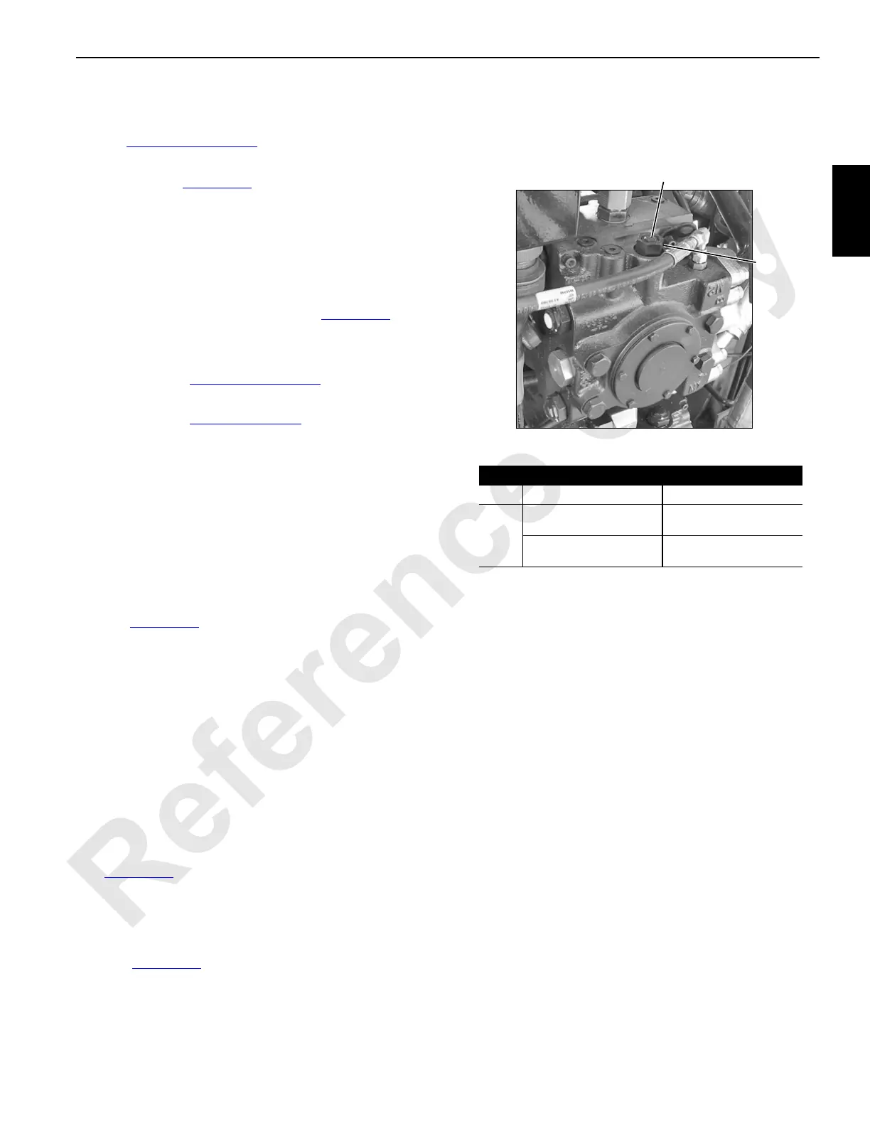
5. To adjust the charge pressure:
See Figure 2-25
for the following procedure:
a. Loosen the lock nut (1).
b. Adjust the adjusting plug (2):
- Turn IN to increase the pressure
- Turn OUT to decrease the pressure
c. Once the specified pressure is indicated, hold the
adjusting plug (2) in position and securely tighten
the lock nut (1).
6. Stop the engine and remove the gauge from the
transducer gauge port.
Pump Neutral Adjustment
See Figure 2-26 for the following procedure.
To adjust pump neutral:
1. Park all the crane functions and stop the engine.
2. Disconnect the electrical connector from the pump EDC
(see Figure 2-29
).
3. Install an accurate 0 to 69 bar (0 to 1,001 psi) hydraulic
pressure gauge in each servo gauge port (1).
4. Start and run the engine at high idle.
5. Loosen the lock nut (2).
6. Using an internal hex wrench, turn the adjusting screw
(3) IN until the pressure increase in either gauge.
7. Note the angular position of internal hex wrench.
8. Then, turn the adjusting screw OUT until pressure
increases an equal amount in the other gauge.
9. Again, note the angular position of the internal hex
wrench.
10. Turn the adjusting screw in half the distance between
the positions noted above.
11. The pump control should now be in neutral with both
gauges reading the same pressure.
12. Hold the adjusting screw (3) in position and securely
tighten the lock nut (2).
13. Stop the engine, remove the gauges, and securely
install the servo gauge port plugs (1).
Item Description Hex Wrench Size
1 Lock Nut 12,7 mm (1/2 in)
2
Adjusting Plug
Series 030-100
27 mm (1-1/16 in)
Adjusting Plug
Series 030-100
41,3 mm (1-5/8 in)
1
P1600a
FIGURE 2-25
2
Typical Pump Installation