Manitowoc Published 05-03-17, Control # 228-03 1-49
16000 SERVICE/MAINTENANCE MANUAL INTRODUCTION
When the front or rear rotating bed pins switch is placed in
the engage position and held, an input voltage is sent to the
Node-1 controller. The Node-4 controller sends a 24 volt
output to enable the rotating bed pins solenoid HS-40 (front
selected) or HS-42 (rear) and shifts the valve to the engage
position. The Node-3 controller sends a variable 0 to 24 volt
output to enable the accessory system proportional relief
solenoid HS-68.
Hydraulic fluid pressure at approximately 204 bar (2,959 psi)
flows to the rotating bed pins accessory valve. Hydraulic fluid
leaves the accessory valve and enters the piston end of the
selected pin cylinders, extending the cylinder rod to engage
the rotating bed pins. Hydraulic fluid from the rod end of the
pin cylinders leaves the accessory system valve and returns
to the tank. When the rotating bed pins switch is released,
the valve returns to the center position.
When the rotating bed pins switch is placed in the
disengage position and held, an input voltage is sent to the
Node-1 controller. The Node-6 controller sends a 24 volt
output to enable the selected front or rear pins solenoid HS-
41 (front) or HS-43 (rear) and shifts the valve to the
disengage position. The Node-3 controller sends a variable
0 to 24 volt output to enable the accessory system
proportional relief solenoid HS-68.
Hydraulic fluid pressure at approximately 204 bar (2,959 psi)
flows to the rotating bed pins accessory valve. Hydraulic fluid
leaves the accessory valve and enters the rod end of the pin
cylinders, retracting the cylinder rods to disengage the
rotating bed pins. Hydraulic fluid from the piston end of the
pin cylinders leaves the accessory system valve and returns
to the tank. When the rotating bed pins switch is released,
the solenoid HS-41 (front) or HS-43 (rear) returns to the
center position. The Node-3 controller sends a variable 0 to
24 volt output to disable the accessory system proportional
relief solenoid HS-68.
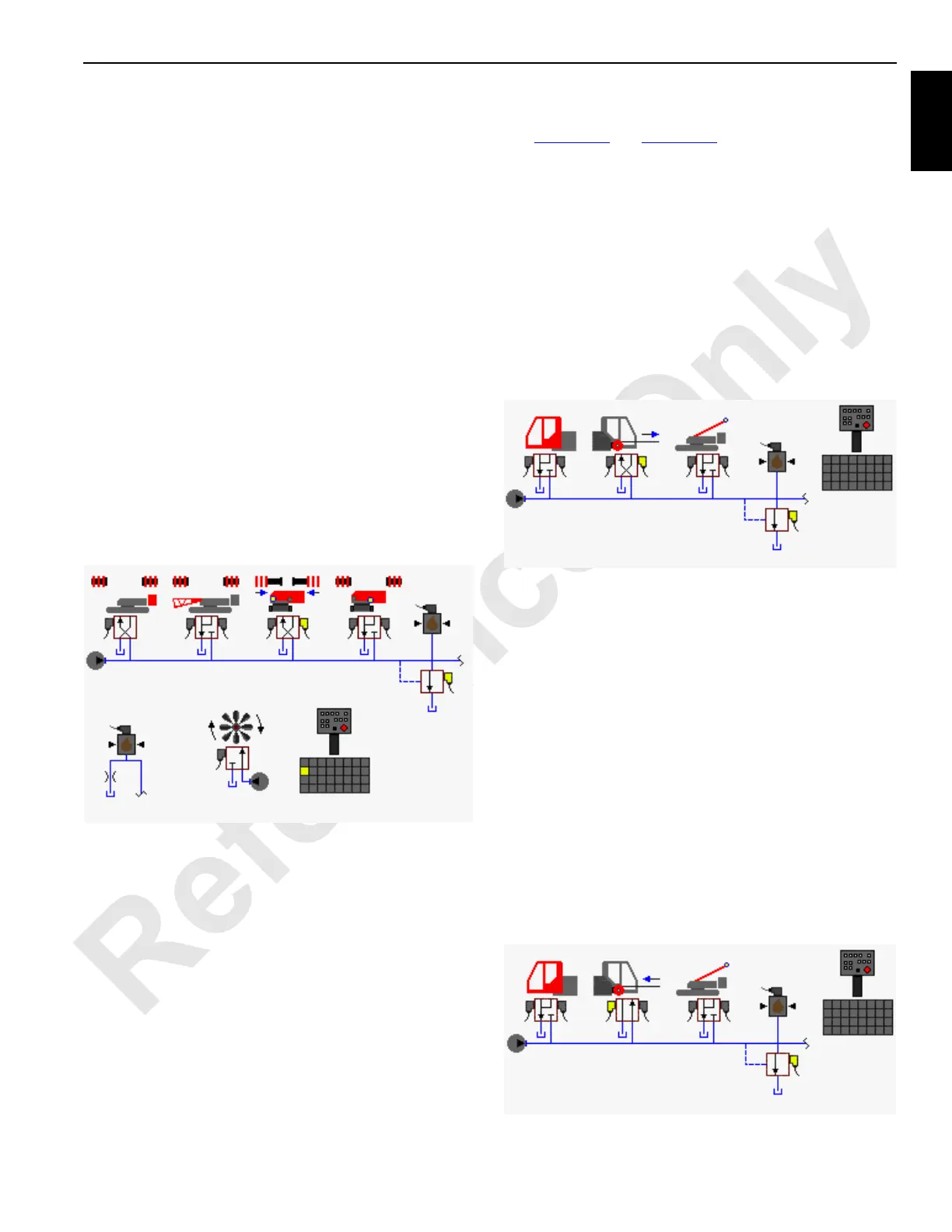
Rigging Winch (Drum 0)
See Figure 1-37 and Figure 1-38.
The rigging winch (Drum 0) is located in the boom butt.
During normal operation the rigging winch solenoid is motor
spooled where both cylinder ports and the tank port of the
valve spool section are connected in the center position.
When an accessory valve spool shifts, supply flow to the
other accessory valves is limited. The accessory system
pressure sender monitors the accessory system pressure.
Access the rigging winch enable screen from the desired
system drum Function Mode screen. When the rigging winch
screen is enabled, the computer selects the handle to
operate the rigging winch. The computer selected handle
display light is 0.
When the selected rigging winch control handle is moved
forward in the pay out position, the Node-4 controller sends
a 24 volt output to enable rigging winch pay out solenoid HS-
55 and shifts the valve to the pay out position. The Node-3
controller sends a variable 0 to 24 volt output to enable the
accessory system proportional relief solenoid HS-68. When
an accessory valve spool shifts, the supply flow to the other
accessory valve is limited. The accessory system pressure
sender monitors the accessory system pressure.
Control handle movement controls the proportional relief
valve hydraulic flow to the rigging winch accessory valve.
Hydraulic fluid leaves the accessory valve and enters the
pay out side of the winch motor to pay out wire rope. Return
hydraulic fluid from the motor leaves the accessory system
valve and returns to the tank. When the rigging control
handle is moved to neutral, the accessory valve returns to
the center position. The Node-3 controller sends a zero volt
output to disable the accessory system proportional relief
solenoid HS-68.
FIGURE 1-36
Pressure
Sender
Front Rotating
Bed Pins
Hand-Held
Wireless Remote
HS-68
HS-41
HS-40
Engine Pump
16-1031
Accessory Pump
(Low-Pressure)
HS-43
HS-42
FIGURE 1-37
Pressure
Sender
Accessory
Pump
Rigging Winch
HS-68
HS-55
HS-54
16-1032
500 to 3,000 psi
(35 to 204 bar)
FIGURE 1-38
Pressure
Sender
Accessory
Pump
Rigging Winch
HS-68
HS-55
HS-54
16-1033
500 to 3,000 psi
(35 to 204 bar)