Manitowoc Published 05-03-17, Control # 228-03 3-41
16000 SERVICE/MAINTENANCE MANUAL ELECTRIC SYSTEM
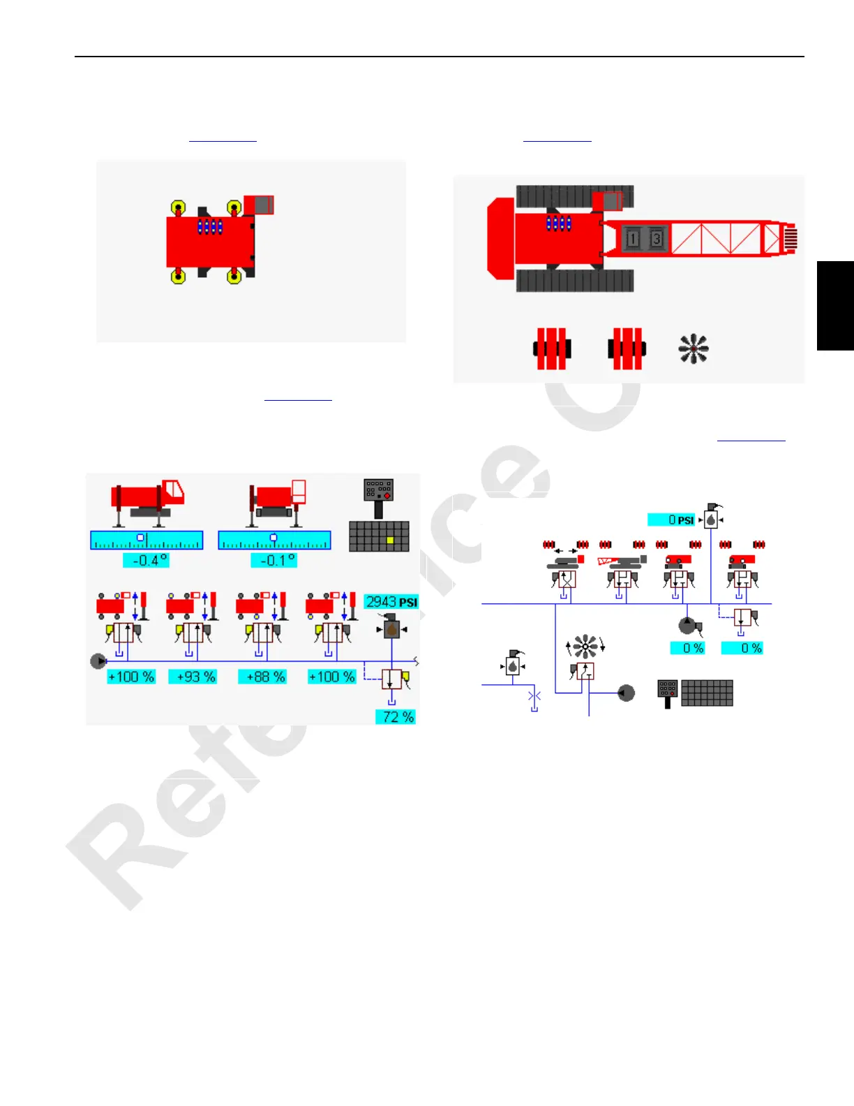
Jacking Accessory Diagnostic Screen
Select the crane carbody with the jacking icon on screen
level 1 as shown in Figure 3-14
. Press the Enter button to go
to level 2.
At the jacking accessory diagnostic screen, the component
icons are displayed as shown in Figure 3-15
. In the following
example, the all jack switch on the wireless remote is
selected. The crane on jacks icons indicate the crane level
status.
Pins and Fan Accessory Diagnostic Screen
Select the crane, pins, and engine fan icon on screen level 1
as shown in Figure 3-16
. Press the Enter button to go to level
2.
For the counterweight pins, boom hinge pins, front/rear
rotating bed pins, and engine fan screen, see Figure 3-17. In
the following example, the left front
rotating bed pin on the
wireless remote is selected.
D16-11
Diagnostic Screen
Accessory Jacking Selected
FIGURE 3-14
Accessory Jacking
(Jacking All Selected)
D16-12
FIGURE 3-15

 Loading...


