ELECTRIC SYSTEM 16000 SERVICE/MAINTENANCE MANUAL
3-44
Published 05-03-17, Control # 228-03
Boom or Swing Motion Limiter Mode
See Figure 3-27 for the following procedure.
NOTE: The motion limiter mode data boxes do not appear
unless the crane has this option.
On level 3, use the select buttons to enable or disable the
motion limiter mode. On level 3 with the motion limiter mode
enabled, the controller monitors and stores the maximum
right/left or up/down angles during operation. After exiting
level 3, these angles are used to limit the boom or swing
motion.
Crane Setup Remote Mode
To turn on the crane setup remote control, see the procedure
in Section 3 of the Operator Manual.
Fan Function
See Figure 3-29 for the following procedure.
The fan speed can be set above a minimum 25% of rated
speed in increments of 5% (for example, 30%, 35%, 40%,
etc...). The minimum fan speed is set at the factory and does
not require further adjustment.
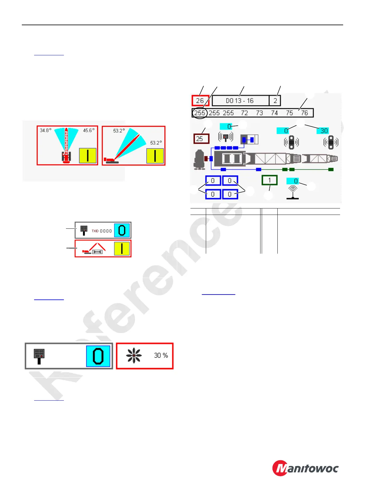
CAN Bus Screen
See Figure 3-30
The CAN (Controller Area Network) bus diagnostic screen is
for technicians. The screen displays CAN bus packet and
node information along with the engine, history, and boom
status. Any node highlighted yellow has lost communication
with the crane.
The CAN Bus screen operates on two levels:
Level 1—The packet number data box is highlighted blue.
Level 2—The packet number data box is highlighted red.
Packet Information
See Figure 3-30, Items 1 through 5 for the following
procedure.
The top row of the screen contains the CAN Bus packet
number (26). Enter the desired packet number in the first
data box using the select buttons.
The packet type (DO in the figure) is displayed in the top
middle data box.
The related node (2 in the figure) is displayed in the top right
data box.
The packet contents are displayed in the eight banks in the
second row. The packet contents and format depend on the
packet type. Many packets are not easily interpreted by non-
Manitowoc technical personnel and are not discussed in this
publication.
Each individual input/output is assigned a number (identifier)
in the binary system (powers of two). The identifiers of all
inputs/outputs that are ON (active) for each bank are added
for a total of 0 to 255. The number displayed for each bank
FIGURE 3-28
Luffing Jib
Setup Screen
Remote
Control
Screen
D16-25C
FIGURE 3-30
Item Description Item Description
1 Packet Number 7 Drum Load Links
2 Packet Type 8 Remote Status
3 Packet Node Number 9 Boom Node Status
4 Packet Banks (8) 10 Wireless Receiver Status
5 Bank 1 Total 11 Crane Status
6 Engine Node Status 12 Crane History
5
12
10
9
4
6
8
1
2
3
7
11