ELECTRIC SYSTEM 16000 SERVICE/MAINTENANCE MANUAL
3-40
Published 05-03-17, Control # 228-03
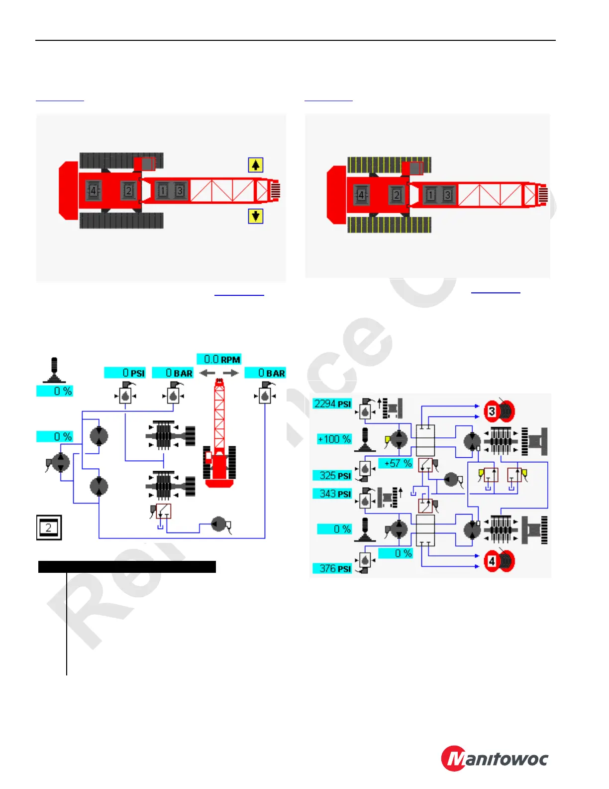
Swing Diagnostic Screen
Select the swing icon on screen level 1 as shown in
Figure 3-10
. Press the Enter button to go to level 2.
The swing system icons are displayed in Figure 3-11
. The
example shows the swing function swinging right. Circular
arrow symbols near each pressure sender indicate which
sender monitors swing right and left pressures.
Travel Diagnostic Screen
Select the travel icon on screen level 1 as shown in
Figure 3-12
. Press the Enter button to go to level 2.
In the travel system example shown in Figure 3-13, the left
travel pump is dedicated to operate drum 3 through a
diverting valve if drum 3 is selected. Under certain conditions
when drum 5 is also configured, the right travel pump is
dedicated to operate drum 4 a through a diverting valve if
drum 4 is selected.
NOTE: When crane travel is enabled, drum 3 is disabled.
FIGURE 3-10
D16-07
Diagnostic Screen
Swing Selected
HS-1
Item Description
1 Swing Handle Command in Percent
2 Swing Pump Command in Percent
3 Swing Motors
4 Swing Brake Solenoid HS-1
5 Accessory Pump (low pressure)
6 Swing Brake
7 Swing Brake Pressure Sensor
8 Swing Right Pressure Sensor
9 Swing Left Pressure Sensor
1
2
3
7 8
6
5
4
9
FIGURE 3-11
D16-09
Diagnostic Screen
Travel Selected
FIGURE 3-12
D16-10B
Left Travel Selected
FIGURE 3-13