Manitowoc Published 05-03-17, Control # 228-03 3-39
16000 SERVICE/MAINTENANCE MANUAL ELECTRIC SYSTEM
Drum Diagnostic Screens
Select the drum icon on screen level 1 as shown Figure 3-8.
Press the Enter button to go to level 2.
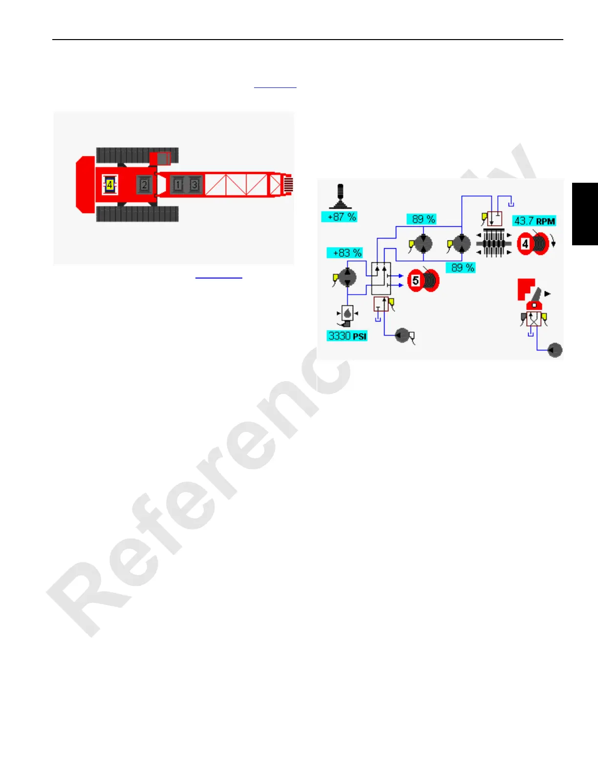
In the drum example shown in Figure 3-9
, the drum 4
function is shown hoisting up. A single pump is shared with
drum 5 and is connected to drum 4 through a diverting valve.
A second pump could also power drum 4, shown connected
to the left track through an upper diverting valve.
NOTE: Mast hoist drum 5 is only selected when the crane
is configured with a MAX-ER.
For load drums 1 or 2, the drum 2 pump is dedicated to the
drum 1 motor through a diverting valve when drum 1 is
selected. The opposite is true when drum 2 is selected. Both
drums can be operated at the same time but would operate
at half speed.
For load drum 3, the left travel pump is dedicated to operate
the drum 3 motor through a diverting valve when drum 3 is
selected. Drum 3 is inoperable when traveling. Drum 3 can
be configured as a load drum or luffing jib.
FIGURE 3-8
Diagnostic Screen
Drum 4 Selected
D16-05
Drum 4 Selected
D16-06B
FIGURE 3-9