INTRODUCTION 16000 SERVICE/MAINTENANCE MANUAL
1-40
Published 05-03-17, Control # 228-03
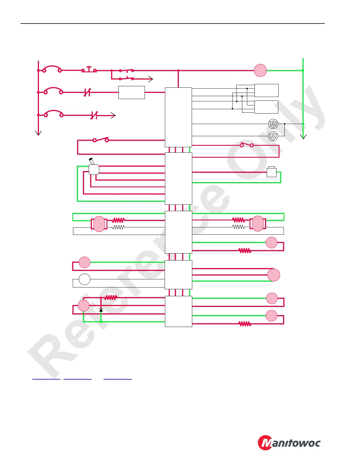
Drum 2 Electrical Schematic
LOAD/LUFFING DRUM 3
System Components
See Figure 1-26, Figure 1-27 and Figure 1-28.
The load/luffing drum 3 is located in the boom butt. The drum
can be configured either for luffing jib operation or as an
auxiliary drum. If drum 3 is rigged for luffing jib operation it
cannot be used as a load drum.
One hydraulic pump drives one motor gearbox on the left
side end of drum 3. The left travel pump is dedicated to
operate drum 3 though a diverging valve. The left track and
drum 3 cannot be operated at the same time. Hydraulic
connections between the pump and the motor form a closed-
loop system that is controlled with the control handle
movement and node controllers. The far load drum control
handle on the right side console operates drum 3 when
configured as a load drum. When configured as a luffing jib,
the control handle on the left side console operates drum 3.
DI P12-26
D0 52-32
Seat Switch
HS
16
Drum 1
Drum 2
Diverting
Gnd 43-D
DO 43-C
Drum2
Drum 1
Diverting
HS
21
Gnd 43-F
DO 43-E
Hyd
Psi
43-k Gnd
43-V 24 Volts
43-d AI
EDC
Gnd 34-G
Gnd 34-E
DO34-H
DO 34-F
Pump 4
Drum 1
Drum 2
EDC
34-K Gnd
34-L Gnd
34-S DO
34-M DO
Pump 6
Drum 2
Drum 1
+
–
PWR
CAB
System Fault Alarm
RCL Cab Fault Alarm
P11-07
P11-19
Display 1
Display 2
P11-01
P12-31
P12-32
P11-21
Start
WCP
CAN Power
Run 3
P12-24
Cab Power
Engine Stop
10 Amp
50 Amp
24 Volts
50 Amp
6C5A
6C5
CB7
6A
6C7
6C14
CB5
CB8
8C
8
HS
20
M/C
FIGURE 1-25
Drum 2
Park Brake
NODE 2
NODE 0
NODE 3
NODE 1
(Master)
NODE 4
NODE 5
DI P12-14
DO P52-07
DO P52-17
DI P51-08
DO P52-16
5 Volts P52-34
AI P51-04
Gnd P51-22
56-D DO
P52-25 Gnd
P52-02 DO
56-C Gnd
56-A Gnd
56-B DO
Drum 2
Control Handle
Handle
Rotation
Indicator
Drum 2
Pressure
Sender
RS Drum 2
Motor
Control
Drum 2
Brake
M/C
36-C Gnd
36-D DO
LS Drum 2
Motor
Control
SS
DO 56-g
EC1B 56-p
Drum 2 Motor
Speed Sensor
Gnd 56-j
EC1A 56-n
Raise
Lower
Raise
Lower
16-1020