INTRODUCTION 16000 SERVICE/MAINTENANCE MANUAL
1-38
Published 05-03-17, Control # 228-03
When the system pressure exceeds the PCOR (Pressure
Compensating Over-Ride) valve setting of 340 bar (4,930
psi), the valve shifts to direct the flow from the shuttle valve
into the maximum displacement side of the servo cylinder.
The PCOR valve over-rides the command from the servo PC
valve, increasing the motor displacement and the output
torque while reducing the output speed. When the PCOR
valve closes, control of the motor returns to the servo PC
valve.
The node controllers continuously balance the drum system
pressures and monitor the motor displacement angle so
motor displacement goes to the minimum when the control
handle is all the way back, if motor torque requirements are
not too high. The Node-1 controller monitors the motor
displacement and controls the motor speed by regulating the
hydraulic fluid flow through the pumps.
When the drum control handle is moved to the neutral
position, The Node-1 controller compensates for the
hydraulic system leakage or changing engine speed. The
Node-3 controller sends a zero output voltage to each pump
EDC that moves the swashplate to the center position. This
shifts the motors back to the maximum displacement for
slower output speed to slow the drum rotation.
When the control handle is moved to the neutral position, the
Node-1 controller stores the load holding pressure in the
pressure memory. After the control handle center switch
opens, the Node-5 controller sends a zero output voltage to
disable the drum brake release solenoid HS-20. The drum
brake solenoid valve shifts to block the pilot pressure to the
brakes and opens a line to the tank. The brakes apply before
the drum pumps de-stroke.
When the brake applies, an input signal is sent to the Node-1
controller. The Node-3 controller sends a zero volt output to
each pump EDC to de-stroke pumps. The Node-3 and 5
controllers send a zero volt output to each motor PCP.
The drum 1 to drum 2 diverting solenoid HS-16 remains
enabled until drum 1 handle is moved.
Lowering Load
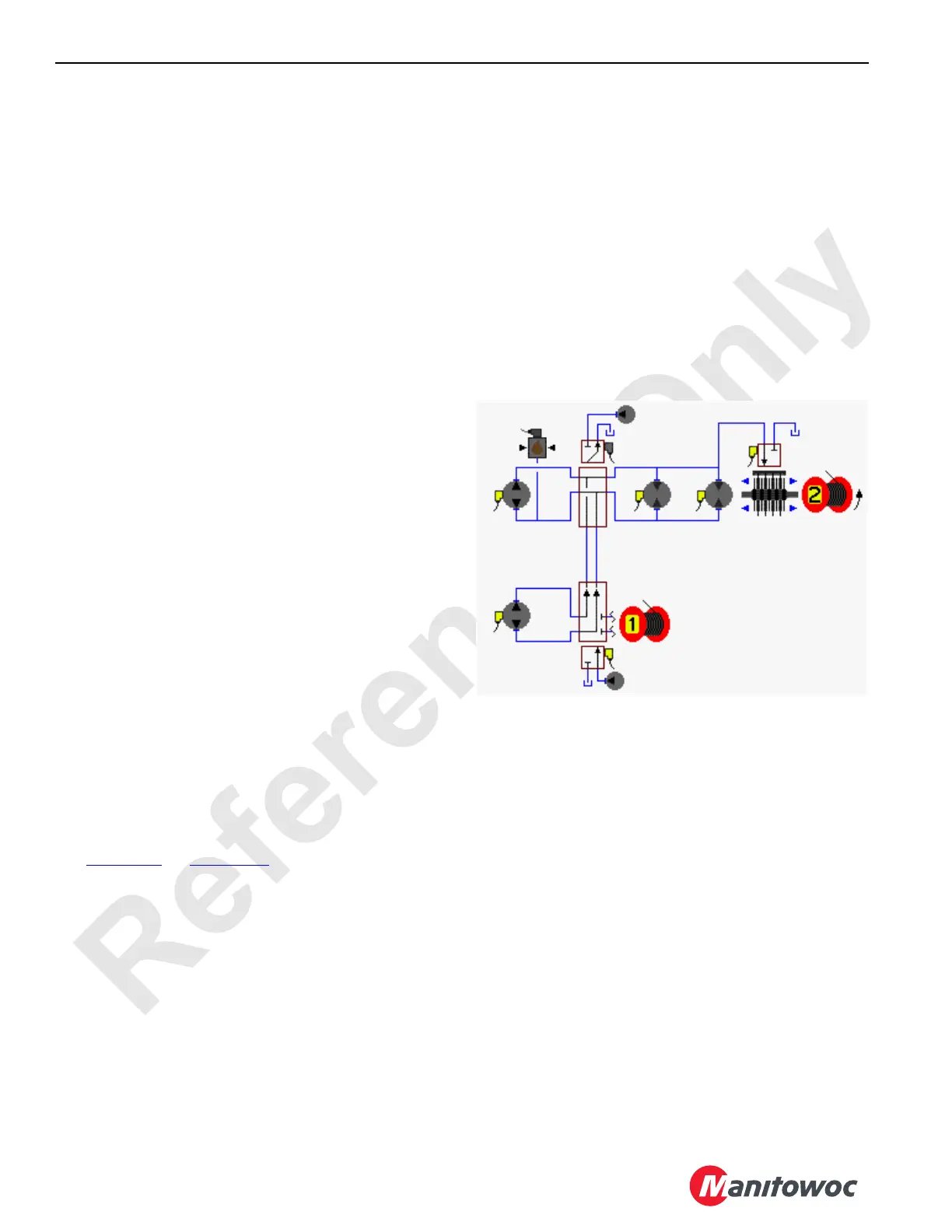
See Figure 1-24 and Figure 1-25.
When the drum 2 control handle is moved forward for
lowering, an input voltage of 2.6 volts or more is sent to the
Node-1 controller. The Node-3 controller sends a variable 0
to 24 volt output that is divided by a resistor and applied to
the pump 6 EDC in the raising direction. The Node-4
controller sends a 24 volt output to enable the drum 1 to
drum 2 diverting solenoid HS-16. The Node-3 controller
sends a variable 0 to 24 volt output that is divided by a
resistor and applied to the pump 4 EDC in the raising
direction. Both pumps supply the hydraulic fluid to the drum 2
motors. The Node-3 and 6 controllers send a variable 0 to 24
volt output that is divided by a resistor and applied to both the
motor PCP’s. The Node-1 controller checks that the drum
block-up limit switches are closed and no system faults are
present.
The pump EDC tilts the swashplate in the raising direction to
satisfy the pressure memory. The Node-1 controller
compares the drum holding pressure to the value in the
pressure memory. When the system pressure is high
enough, the Node-6 controller sends a 24 volt output to
enable the drum 2 brake release solenoid HS-20. The drum
brake solenoid shifts to block the drain port and opens the
port to low-pressure side of drum system to release the
brake from the drum shaft.
Each pump EDC tilts the swashplate in the lowering
direction as the hydraulic fluid flow is from the pump ports to
the motor ports. Return fluid is from the motor outlet ports to
the pump inlet ports.
The Node-3 controller output voltages to each pump EDC
and the Node-3 and 5 controllers output voltage to each
motor PCP is relative to the control handle movement. As the
control handle is moved back, an output voltage increases
the pumps swashplate angles.
NOTE: If drum 1 is selected to be operated at the same
time, the Node-4 controller sends a 24 volt output
to the disable drum 1 to drum 2 diverting solenoid
HS-16. Drum 2 speed is reduced up to one half.
When the system pressure exceeds the PCOR (Pressure
Compensating Over-Ride) valve setting of 340 bar (4,931
psi), the valve shifts to direct flow from the shuttle valve into
the maximum displacement side of the servo cylinder. The
PCOR valve over-rides the command from the servo PC
valve, increasing the motor displacement and the output
torque while reducing the output speed. When the PCOR
valve closes, the control of the motor returns to the servo PC
valve.
The node controllers continuously balance the drum system
pressures and monitor the motor displacement angle so the
motor displacement goes to the minimum when the control
FIGURE 1-24
HS-7
HS-20
HS-16
HS-21
Brake
Diverting
Valve
Motors
(PCP)
Pump
(EDC)
Pressure
Sender
Pump
(EDC)
16-1019
Accessory Pump
(Low-Pressure)
Accessory
Pump (Low-
Pressure)