HYDRAULIC SYSTEM 16000 SERVICE/MAINTENANCE MANUAL
2-22
Published 05-03-17, Control # 228-03
HYDRAULIC SYSTEM TEST, CALIBRATION,
AND ADJUSTMENT PROCEDURES
It is only necessary to perform the following procedures at
the specified intervals or when instructed to do so during
troubleshooting (see Section 10).
Pressure Test and Calibration Screen
NOTE: To understand the operation of the main display
and touch pad controls, read the instructions in
Section 3 or the 16000 Operator Manual.
The Pressure Test and Calibration Screen (see Figure 2-19
)
is used to initiate and monitor the four hydraulic test and
calibration procedures described in this section.
The screen shows the pump commands and pressure levels
for all primary crane functions. Use the data box in the upper
left corner of the screen to select and start a specific test or
calibration procedure.
The pressure Test and Calibration screen operates on two
levels.
Level 1—Test data box highlighted blue
Level 2—Test data box highlighted red. Use Select buttons
to choose the test or calibration procedure
All test and calibration procedures must be run at a particular
engine speed. If a test is started at the wrong speed, the
appropriate prompt shown below appears in the data box
and the procedure is aborted.
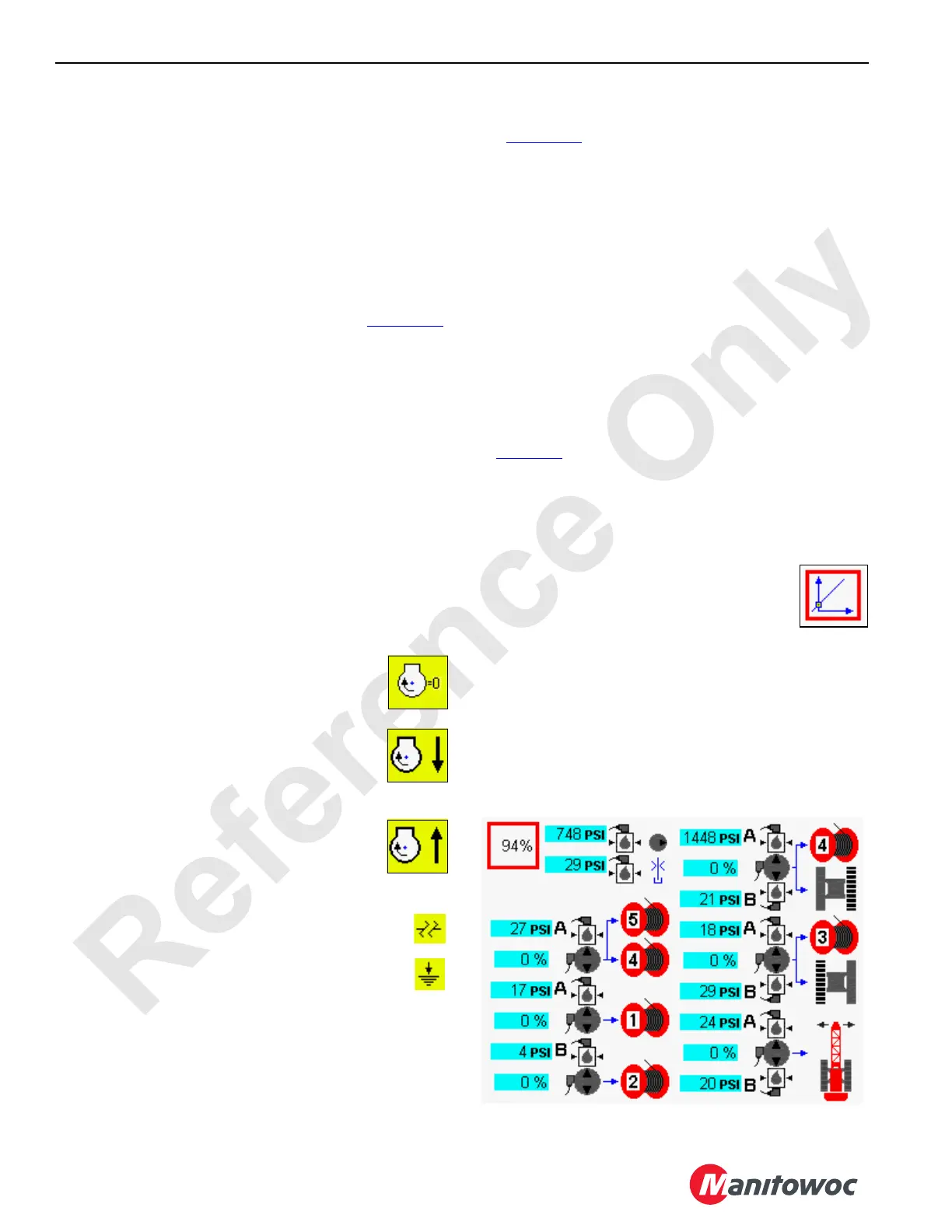
Engine Off
The yellow engine pressure 0 icon indicates that
the test must be run with the engine off.
Engine Low Idle
The yellow engine pressure down arrow icon
indicates that the test must be run with the engine
at low idle.
Engine High Idle
The yellow engine pressure up arrow icon
indicates that the test must be run with the engine
at high idle.
The yellow open-circuit icon indicates a circuit fault
that must be serviced immediately.
The yellow short-to-ground icon indicates a circuit
fault that must be serviced immediately.
Pressure Sender Test
See Figure 2-19 for the following procedure.
The pressure sender test calculates the zero-pressure
output level for each pressure sender. Pressure sender null
(0) must be with in 0.65 to 1.35 volts.
Perform this test when the following situations occur:
- A new pressure sender is installed
- A new controller node that monitors pressure
senders is installed
- A new master node or master node software is
installed
- Pressure readings are noticeably in error
Be aware that if there is any residual pressure in the system
during the calibration process, the display pressure reading
in the cab may not reflect actual system pressure. See Note
on page 2-23
.
Test pressure senders using the following procedure:
1. Stop the engine and turn the ignition switch to the run
position. Push the Enter button to go to the Pressure
Test and Calibration screen from the Menu screen.
2. Press the Enter button to go to level 2. Use
the Select buttons to show the PRESSURE
SENDER icon in the data box.
3. Press the Confirm button to start the test.
4. The test starts and the percent of completion is
displayed in the data box.
5. When the test is complete, the pressure sender icon
reappears in the data box.
The pressure senders must show a signal within a specified
range during this test. Any sender signal out of this range is
highlighted in yellow. Troubleshoot the failed senders to
determine the cause of the fault.
FIGURE 2-19
D16-26AA
Data
Box

 Loading...


