Manitowoc Published 05-03-17, Control # 228-03 1-33
16000 SERVICE/MAINTENANCE MANUAL INTRODUCTION
LOAD DRUM 1
System Components
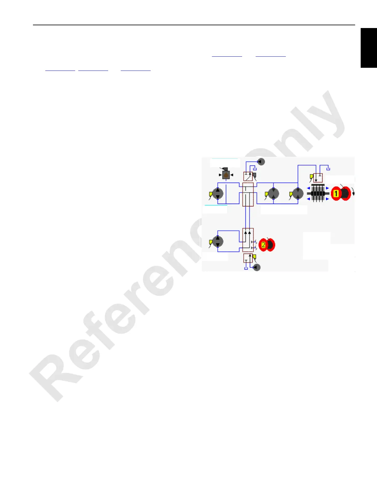
See Figure 1-20, Figure 1-21 and Figure 1-22.
Load drum 1 is located in the boom butt. One hydraulic pump
drives two separate motor gearboxes on each end of the
drum. The load drum 2 pump is dedicated to operate with
load drum 1 though a diverging valve. The hydraulic
connections between the pump and the motors form a
closed-loop system that is controlled with the control handle
movement and node controllers. The left load drum control
handle on the right side console operates drum 1. The
control handle is inoperable when drum 1 park brake is
applied.
Hydraulic charge pressure from the system charge pump
supplies hydraulic make-up fluid to the low-pressure side of
each drum 1 motor. A pressure sender in the high-pressure
side of the pump leg provides system pressure information to
the Node-1 controller. The low-side pressure supplies the
hydraulic pilot pressure to operate motor servos. A fixed
orifice between the pump ports A and B allows for smoother
drum operation.
When load drum 1 motors rotate, a speed sensor at one
motor rotor monitors and sends an input voltage to the Node-
1 controller. The Node-2 controller sends an output voltage
to the rotation indicator in the control handle. As the drum
rotates faster, the rotation indicator on top of the control
handle pulsates with a varying frequency that indicates the
drum rotational speed. The handle command in percent from
neutral is shown on the Diagnostic Screen.
Continuous changing of closed-loop fluid occurs with
leakage in the pump, the motor, and the external sequence/
flow valve. The sequence/flow valve opens at 14 bar (203
psi) and removes 15 Lpm (4 gpm) of hot fluid from the
system by discharging the exhausted fluid into the motor
case where the fluid returns to the tank.
Load Drum 1 Brake
Hydraulic pressure to operate the drum 1 brake is from the
low-pressure side of the system.
When the drum 1 brake switch is in the ON-park position, the
drum brake release solenoid HS-15 is disabled so the brakes
are applied to each side of the drum shaft. The drum pump
does not stroke in response to the control handle movement.
When the drum 1 brake switch is placed in the OFF-park
position, the brake release solenoid HS-15 remains applied.
Brakes remain applied until the Node-6 controller sends a 24
volt output to release the brake. The drum circuit is active,
waiting for a control handle command.
Raising Load
See Figure 1-20 and Figure 1-22. When the drum 1 control
handle is moved back for raising, an input voltage of 2.4 volts
or less is sent to the Node-1 controller. The Node-3 controller
sends a variable zero to 24 volt output that is divided by a
resistor and applied to the pump 4 EDC in the raising
direction. The Node-4 controller sends a 24 volt output to
enable the drum 2 to drum 1 diverting solenoid HS-21. The
Node-3 controller sends a variable zero to 24 volt output that
is divided by a resistor and applied to the pump 6 EDC in the
raising direction. Both pumps supply hydraulic fluid to the
drum 1 motors. The Node-6 controller sends a variable zero
to 24 volt output that is divided by a resistor and applied to
both drum 1 motor PCP’s. The Node-1 controller checks that
the drum block-up limit switches are closed and no system
faults are present.
The pump EDC tilts the swashplate in the raising direction to
satisfy the pressure memory. The Node-1 controller
compares drum holding pressure to the value in the pressure
memory. When system pressure is high enough, the Node-6
controller sends a 24 volt output to enable the drum 1 brake
to release solenoid HS-15. The drum brake solenoid shifts to
block the drain port and opens the port to the low-pressure
side of the drum system to release the brake from the drum
shaft.
Each pump EDC tilts the swashplate in the raising direction
as hydraulic fluid flow is from the pump ports to the motor
ports. Return fluid is from the motor outlet ports to the pump
inlet ports.
The Node-3 controller output voltages to each pump EDC
and the Node-6 controller output voltage to each motor PCP
is relative to the control handle movement. As the control
handle is moved back, an output voltage increases the
pumps swashplate angles.
NOTE: If drum 2 is selected to be operated at the same
time, The Node-4 controller sends a 24 volt output
to disable the drum 2 to drum 1 diverting solenoid
HS-21. Drum 1 speed is reduced up to one half.
HS-15
HS-21
HS-16
Brake
Diverting
Valve
Pump
(EDC)
Pressure
Sender
Pump
(EDC)
16-1015
Accessory Pump
(Low-Pressure)
Motors
(PCP)
Accessory
Pump (Low-
Pressure)
FIGURE 1-20