Manitowoc Published 05-03-17, Control # 228-03 3-49
16000 SERVICE/MAINTENANCE MANUAL ELECTRIC SYSTEM
Camera Screen (Optional)
The camera screen sets the desired camera operation. The
camera option includes up to three different cameras to
monitor drum spooling and the area behind the crane.
Use the select buttons to select the camera screen from the
menu screen. Press the enter button to access the screen.
Use the select buttons to select the desired camera view.
When done, press the exit button until the menu screen
appears.
Pressure Test and Calibration Screen
The pressure test and calibration screen initiates and
monitors the hydraulic test and calibration procedures. For
instructions to run these tests, refer to Section 2.
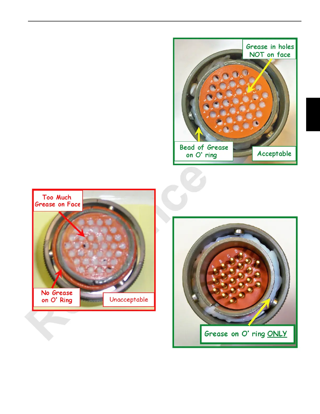
DIELECTRIC GREASE
The following figures show the proper application of
dielectric grease on all J-tech type connectors.
Dielectric grease is needed when assembling the J-tech type
connectors. Apply a bead of grease on the o-ring and face of
the socket connector. Apply a bead of grease on the o-ring of
the pin connector. Do not apply grease to the face of the pin
connector.
Use the following sizes when applying the bead of grease:
• On a 3-pin connector, apply a 1,5 mm (1/16 in.) bead.
• On a 24-pin connector, apply a 3 mm (1/8 in.) bead.
• On a 37-pin connector, apply a 5 mm (3/16 in.) bead.
To apply the grease to the connector face, place a small
amount of grease on your finger. Wipe your finger across the
face, applying grease inside the socket holes with a layer
less than 0,025 mm (0.001 in.) on the connector face. This
keeps water out of the connectors and keeps the pins from
fretting.

 Loading...


