INTRODUCTION 16000 SERVICE/MAINTENANCE MANUAL
1-52
Published 05-03-17, Control # 228-03
sends a zero volt output to disable the accessory system
proportional relief solenoid HS-68.
When a carbody jack handle is moved forward to lower, the
valve shifts to allow system pressure to the jack cylinder. The
lower accessory enable pressure sender senses a pressure
drop and sends an input signal to the Node-1 controller. The
Node-3 controller sends a variable 0 to 24 volt signal to
accessory system proportional relief solenoid HS-68 to
increase the relief valve setting to approximately 207 bar
(3,002 psi). The system pressure increases to operate the
selected jack handle. The Node-1 controller monitors the
system pressure.
Hydraulic fluid enters the rod end of the cylinder, retracting
the cylinder rods, lowering the carbody and the upperworks.
Hydraulic fluid from the piston end of the cylinder flows
through the lower accessory valve and is returned to the
tank.
When the handle is moved back to the center position, the
selected valve shifts to the center position and opens the line
to the cylinders. The Node-3 controller sends a zero-volt
output to disable the accessory system proportional relief
solenoid HS-68.
Live Mast
See Figure 1-43, Figure 1-44, Figure 1-45, and Figure 1-46.
The live mast is the rectangular shaped structure that
supports the boom. The mast is also used for crane
assembly and disassembly.
The mast-raising sequence is controlled automatically by the
computer program and the boom/mast hoist control handle.
The mast raising and lowering rate is controlled by the
engine speed, as it regulates the pay out and the haul in of
the cable reeving between the boom/mast hoist sheaves and
the mast sheaves.
The mast system faults appear on the information screen
when the mast is inoperable in either direction or the mast is
at the maximum lower position. Stop operating when a fault
appears.
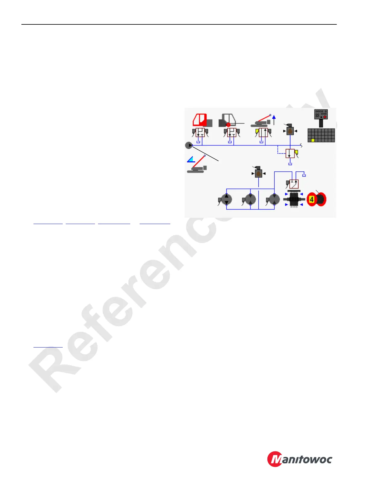
Mast Raising/Lowering with Mast Switch
See Figure 1-43.
The mast switch on the hand-held wireless remote should
only be used for raising/lowering the mast cylinders without
wire rope rigging. Power is available to the hand-held
wireless remote control when the engine is running, and the
power button is pressed.
When not enabled, the mast raising cylinders are motor
spooled where both cylinder ports and the tank port of the
valve spool section are connected in the center position. This
type of spool prevents the premature opening of the
equalizing valves. The load equalizing valves ensure the
mast-raising cylinders operate in unison, protecting the mast
from structural damage caused by twisting. The load
equalizing valves also provides the support resistance
against the mast to ensure the control of the unit while
rotating it at assembly. When an accessory valve spool
shifts, supply flow to the other accessory valves is limited.
The accessory system pressure sender monitors the
accessory system pressure.
When the mast cylinders switch is placed in the raise
position and held, an input voltage is sent to the Node-1
controller. The Node-4 controller sends a 24 volt output to
enable the mast cylinders raise solenoid HS-50 and shifts
the valve to the raise position. The Node-3 controller sends
a variable 0 to 24 volt output to enable the accessory system
proportional relief solenoid HS-68. See the automatic
raising/lowering procedure below for the complete cylinder
operation.
When the mast cylinder switch is released, solenoid HS-50
returns to the center position. The Node-3 controller sends a
zero volt output to disable the accessory system proportional
relief solenoid HS-68.
When the mast cylinders switch is placed in the lower
position and held, an input voltage is sent to the Node-1
controller. The Node-4 controller sends a 24 volt output to
enable the mast cylinders lower solenoid HS-51 and shifts
the valve to the lower position. The Node-3 controller sends
a variable 0 to 24 volt output to enable the accessory system
proportional relief solenoid HS-68. See the automatic
raising/lowering procedure below for the complete cylinder
operation.
When the mast cylinder switch is released, the solenoid HS-
50 returns to the center position. The Node-3 controller
sends a zero volt output to disable the accessory system
proportional relief solenoid HS-68.
FIGURE 1-43
Pressure
Sender
Accessory
Pump
Mast
Raising
Cylinders
Hand-Held
Wireless
Remote
HS-68
HS-51
HS-50
16-1036
500 to 3,000 psi
(35 to 204 bar)