ELECTRIC SYSTEM 16000 SERVICE/MAINTENANCE MANUAL
3-6
Published 05-03-17, Control # 228-03
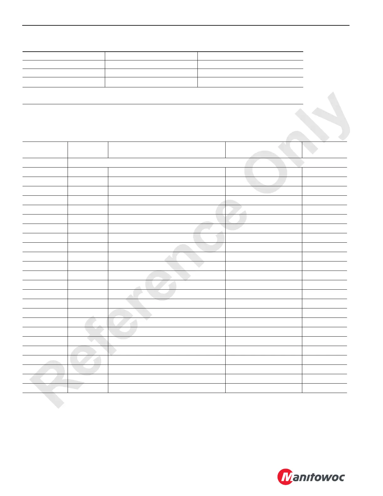
Table 3-2. Pump and Motor Control Test Voltages
Node 1 — Master (Front Console)
Reference Electrical Schematic A10871, Sheet 1, 4, 5, and 14.
All Hoist Pumps Boom and Mast Hoist Motors Load and Luffing Hoist Motors
0 to 25.4 Volts (at Node) 0 to 18.8 Volts (at Node) 0 to 16 Volts (at Node)
0 to 2.0 Volts (at Pump) 0 to 1.9 Volts (at Motor) 0 to 1.6 Volts (at Motor)
0 to 100 mA
1
0 to 75 mA
1
0 to 65 mA
1
1
Resistance increases as temperature rises on the pump or motor control coil resulting in decreased current
values when measured with a meter. The listing in the table is the current range for a 21°C (70
°F) coil.
Connector
Function
Type
Description Test Voltages
CAN Packet
Number
P11 Receptacle – Front Console (Unused Terminals are Omitted)
P11-1 24 Volts Power from Node-3 to Node-1 24 Volts Nominal N/A
P11-3 DI-12 Display Scroll Up Switch 0 Volts Off, 24 Volts On CAN129-4-8
P11-4 DI-14 Display Scroll Down Switch 0 Volts Off, 24 Volts On CAN129-4-32
P11-5 DI-31 Display Exit Switch 0 Volts Off, 24 Volts On CAN129-6-64
P11-6 DI-9 Display Enter Switch 0 Volts Off, 24 Volts On CAN129-4-1
P11-7 DO-1 System Operation Alarm 0 Volts Off, 24 Volts On CAN129-1-1
P11-8 DO-3 RCL Warning L.E.D. 0 Volts Off, 24 Volts On CAN129-1-4
P11-10 DO-6 RCL Caution L.E.D. 0 Volts Off, 24 Volts On CAN129-1-32
P11-11 24 Volts Power to Membrane (Display) Switches 24 Volts Nominal N/A
P11-13 DI-11 Limit Bypass Switch 0 Volts Off, 24 Volts On CAN129-4-4
P11-14 DI-13 Jib Up Limit Bypass Switch 0 Volts Off, 24 Volts On CAN129-4-16
P11-15 DI-32 Load/Luffing (Drum 3) Park Switch 0 Volts Off, 24 Volts On CAN129-6-128
P11-16 DI-10 Confirm Switch 0 Volts Off, 24 Volts On CAN129-4-2
P11-19 DO-7 RCL Fault Alarm in Cab 0 Volts Off, 24 Volts On CAN129-1-64
P11-21 Ground Ground to Node-3 and Displays 1 & 2 Ground N/A
P11-23 DI-28 Travel 2-Speed Switch 0 Volts Off, 24 Volts On CAN129-6-8
P11-24 DI-30 Swing Park Switch – On 0 Volts Off, 24 Volts On CAN129-6-32
P11-25 DI-15 Travel Cruise Switch - On 0 Volts Off, 24 Volts On CAN129-4-64
P11-29 Ground RCL Caution L.E.D. Ground N/A
P11-30 Ground RCL Warning L.E.D. Ground N/A
P11-31 CANH CAN High Data Line to Node-2 N/A N/A
P11-32 CANL CAN Low Data Line to Node-2 N/A N/A
P11-33 DI-27 Display 1 0 Volts Off, 24 Volts On CAN129-6-4
P11-34 DI-29 Display 2 0 Volts Off, 24 Volts On CAN129-6-16