Manitowoc Published 05-03-17, Control # 228-03 3-5
16000 SERVICE/MAINTENANCE MANUAL ELECTRIC SYSTEM
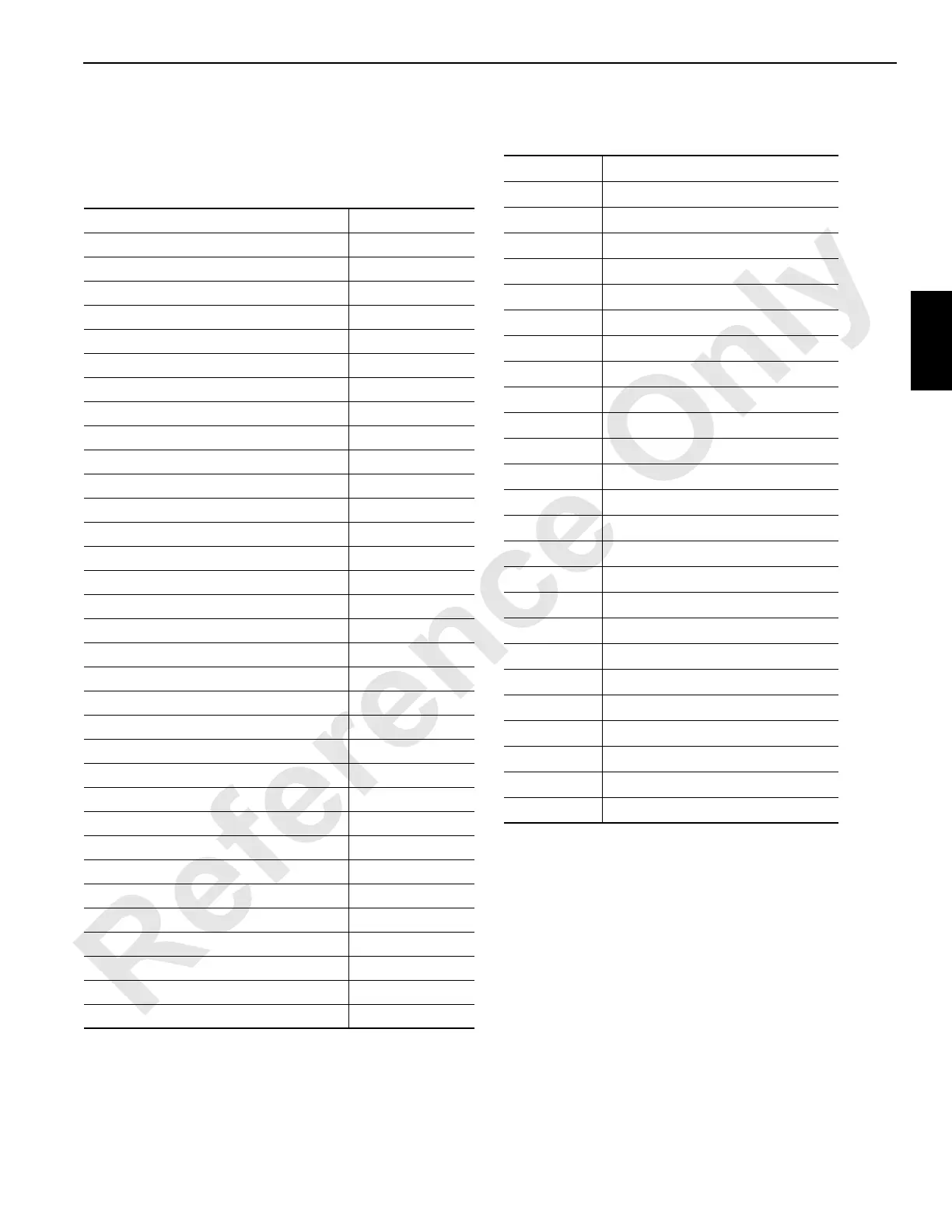
Component–Node Cross-Reverence
Find the desired component item in this index. Check the
component item node location, then refer to the indicated
node to find the test voltage for that item.
Abbreviations Used in Test Voltage Tables
The test voltage tables use the following abbreviations:
Component Location
Accessory System Components Node 3 & 4
Alarms Nodes 1, 3 & 5
Air Conditioning Clutch Node 1
Auto Lube Pumps Node 5
Block Up Limit (Boom) Node 20
Block Up Limit (Luffing Jib) Node 21
Boom Suspension Load Pin Node 5
Cab Switches and Controls Nodes 1 & 2
Cab Power Node 0
Cab Tilt Node 3
Control Handles Nodes 1 & 2
Counterweight Pins Node 4
Boom/Mast Hoist (Drum 4) Components Nodes 3, 4, 5 & 6
Engine Control Module Node 0
Engine Fuel Level Sensor Node 5
Engine Cooler Fan/Acc Enable Solenoid Node 5
Filters Node 3
Hydraulic Fluid Level and Temperature Node 5
Hydraulic Vacuum Switch Node 3
Limits Nodes 5 & 6
Load Hoist (Drum 1) Components Nodes 3, 4 & 6
Load Hoist (Drum 2) Components Nodes 3, 4 & 5
Load/Luffing (Drum 3) Components Node 6
Mast Node 4
MAX-ER Node 7
Pressure Senders Nodes 3, 4 & 5
Rigging Winch Node 4
Rotating Bed Level Sensor Node 5
Swing Components Nodes 3 & 5
Throttle (Hand and Foot) Node 2
Travel Components Nodes 4 & 5
Wind Speed Indicator (Boom) Node 20
Wind Speed Indicator (Jib) Node 21
Acc Accessory
AI Analog Input
AO Analog Output
CAN Controller Area Network
CANH Controller Area Network - High
CANL Controller Area Network - Low
CTWT Counterweight
DC Direct Current
DI Digital Input
DO Digital Output
EC Encoder Control
GND Ground
ID Identification
L.E.D. Light Emitting Diode
LS Left Side
Min. Minimum
N/A Not Applicable
NS Node Select
PSI or psi Pounds per Square Inch
RCL Rated Capacity Indicator/Limiter
RS Right Side
Sol Solenoid
SW Switch
V Volt or Volts
VDC Volts Direct Current
WWire