HOISTS 16000 SERVICE/MAINTENANCE MANUAL
5-2
Published 05-03-17, Control # 228-03
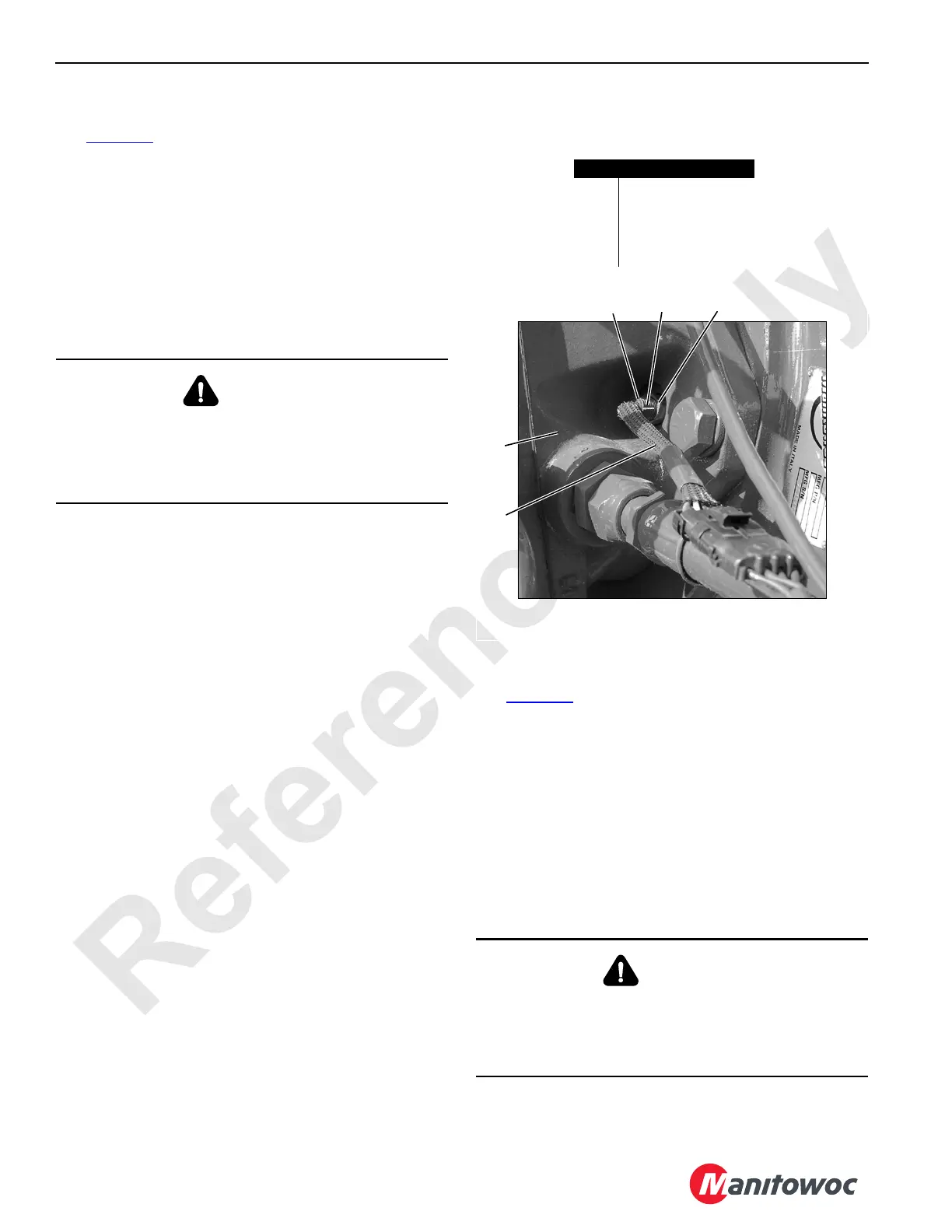
SPEED SENSOR
See Figure 5-2 for the following procedure.
The hydraulic motors for the hoists (boom, mast, load) and
swing have a speed sensor. For those functions with more
than one motor, only one of the motors has a speed sensor.
Each speed sensor monitors the rotational speed and
direction of the corresponding motor. The sensor sends a
signal to a remote node controller that transmits the
information to the crane’s master controller. The master
controller uses the information to control the crane function.
Replacement
When removing the speed sensor from a motor, be careful to
contain the hydraulic fluid that will drain from the motor. After
installing a new sensor, add clean hydraulic oil to the level of
the motor top case drain port before starting the engine.
Adjustment
The speed sensors are set at the factory and should not
need adjustment, unless replaced. In the event the sensors
need adjustment, use the following procedure:
1. Bring the corresponding function to a complete stop,
land any suspended load if a load drum is being
serviced, and park the function.
2. Remove the faulty sensor. Do not connect the sensor
cable (4) to the crane wire harness until the initial
adjustment is made.
3. Loosen the lock nut (3) and carefully turn the sensor(1)
clockwise by hand until it gently contacts the speed ring
inside the motor.
4. Back the sensor out one full rotation or more until the
notch is positioned 180° from the motor shaft (facing the
outboard side of the motor).
5. Connect the sensor cable to the crane wire harness.
6. Operate the drum motor and check for a steady drum
speed (RPM) signal on the corresponding drum
diagnostic screen in the cab.
If necessary, turn the sensor out slightly until the drum
speed (RPM) is steady at a low and high RPM.
7. Hold the sensor in position and securely tighten the lock
nut.
MINIMUM BAIL LIMIT
See Figure 5-3 for the following procedure.
The optional minimum bail limit assembly on Drum 1 (main
hoist) and Drum 2 (auxiliary hoist) is a protective device that
limits how much wire rope can be spooled off either drum.
The minimum bail limit automatically stops the
corresponding drum when there are 3 to 4 wraps of wire rope
remaining on the first layer. The drum can be operated in the
hoist direction when the minimum bail limit switch is
contacted.
Adjusting the minimum bail limit switch requires operating
the drum to spool wire rope off the drum.
WARNING
Burn Hazard!
Hydraulic oil that may be hot will drain from the motor port
when the sensor is removed. Wait for the hydraulic oil to
cool before removing the sensor.
WARNING
Falling Load Hazard!
Do not operate a drum with less than 3 or 4 full wraps of
wire rope remaining on the drum. Doing so can cause the
wire rope to be pulled out of the drum and the load to fall.
P2196
Typical Speed Sensor Location
FIGURE 5-2
Item Description
1 Speed Sensor
2Notch
3 Lock Nut
4 Cable
5 Motor
4
1
5
2
3

 Loading...


