POWER TRAIN 16000 SERVICE/MAINTENANCE MANUAL
7-14
Published 05-03-17, Control # 228-03
EXHAUST ASSEMBLY
See Figure 7-11 for the following procedure. Covers can be
unlatched with a screwdriver and removed to allow access to
the exhaust system and hydraulic tank for service.
The entire exhaust assembly may be raised. The assembly
can be held in the raised position by a rod that is stored on
the exhaust assembly frame.
The exhaust assembly can also be entirely removed if
required for the engine, hydraulic system, or other service.
Do not operate the crane without all covers securely
fastened in place.
Raising the Exhaust Assembly
To raise the exhaust assembly, use the following procedure:
1. Stop the engine and open the battery disconnect switch.
2. Remove the access covers that are on the exhaust
assembly frame.
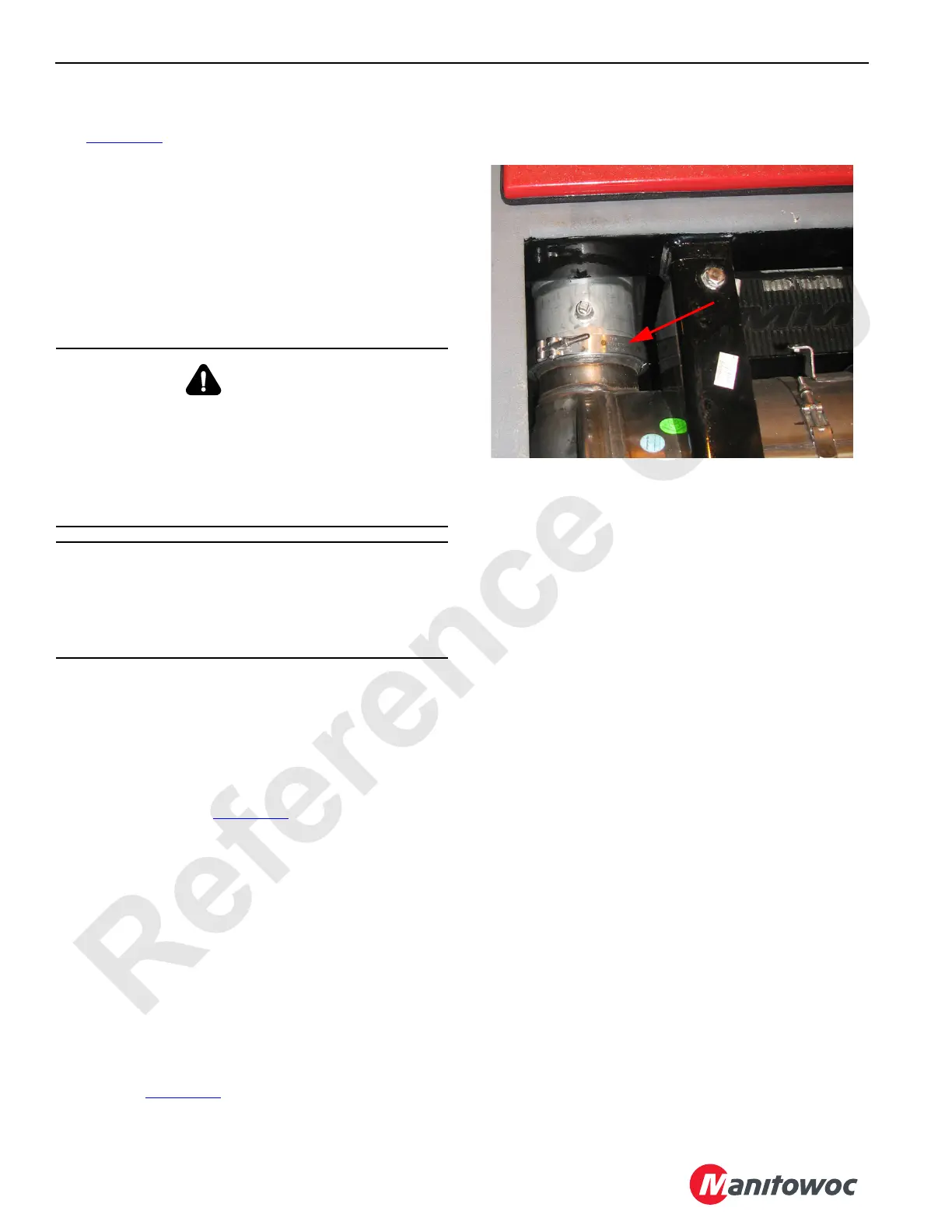
3. Loosen the clamp (Figure 7-10
) that secures the DOC/
DPF module to the bellows exhaust pipe from the
engine.
4. Remove the loosened clamp. Create separation
between the pipe and the module.
5. Remove the rod with the hitch pin from the storage
position inside the forward part of the frame.
6. Remove the hitch pin that is located in the center of the
rear of the frame.
7. Using a crane and appropriate rigging, raise the exhaust
assembly. A cutout in the rear of the frame is provided as
a lifting point.
8. Using the two hitch pins, install the frame support rod as
shown in Figure 7-11
.
9. After service, use a crane to lower the assembly back
into the crane. Place the support rod back into the
storage location.
Removing the Exhaust Assembly
To remove the exhaust assembly, use the following:
1. Stop the engine and open the battery disconnect switch.
2. Remove the covers from the exhaust assembly frame.
3. Remove the DEF and coolant hoses from the DEF
dosing module.
4. Disconnect the electrical connector located above the
dosing module.
5. Disconnect all the electrical connectors for the SCR
module and the DPF module.
6. Raise the exhaust assembly according to the Raising
the Exhaust Assembly procedure.
7. Check that the DEF and coolant hoses are removed
from any clamps that would prevent exhaust assembly
removal.
8. Make sure that all electrical wires are disconnected as
needed and removed from any clamps that would
prevent the exhaust assembly removal.
9. Check for any other components that may interfere with
the assembly as it is removed.
10. Using an assist crane to support the exhaust assembly,
remove the support rod and lower the assembly back
into the crane.
11. Remove both 2-hole pins that secure the front of the
exhaust assembly frame to the crane.
12. Using a 3-point lift at the provided lifting holes, remove
the exhaust assembly from the crane.
WARNING
Crush Hazard
The exhaust assembly weighs approximately 400 kg (880
lb) with the access covers removed. If the assembly falls,
personnel may be crushed.
Use appropriate lifting equipment when raising the
exhaust assembly.
CAUTION
Avoid Electronic Control Module Malfunction
Before disconnecting the batteries, make sure the engine
ignition switch has been off for 70 seconds. This will avoid
engine fault codes and undesirable operation.