INTRODUCTION 16000 SERVICE/MAINTENANCE MANUAL
1-4
Published 05-03-17, Control # 228-03
IDENTIFICATION AND LOCATION OF COMPONENTS
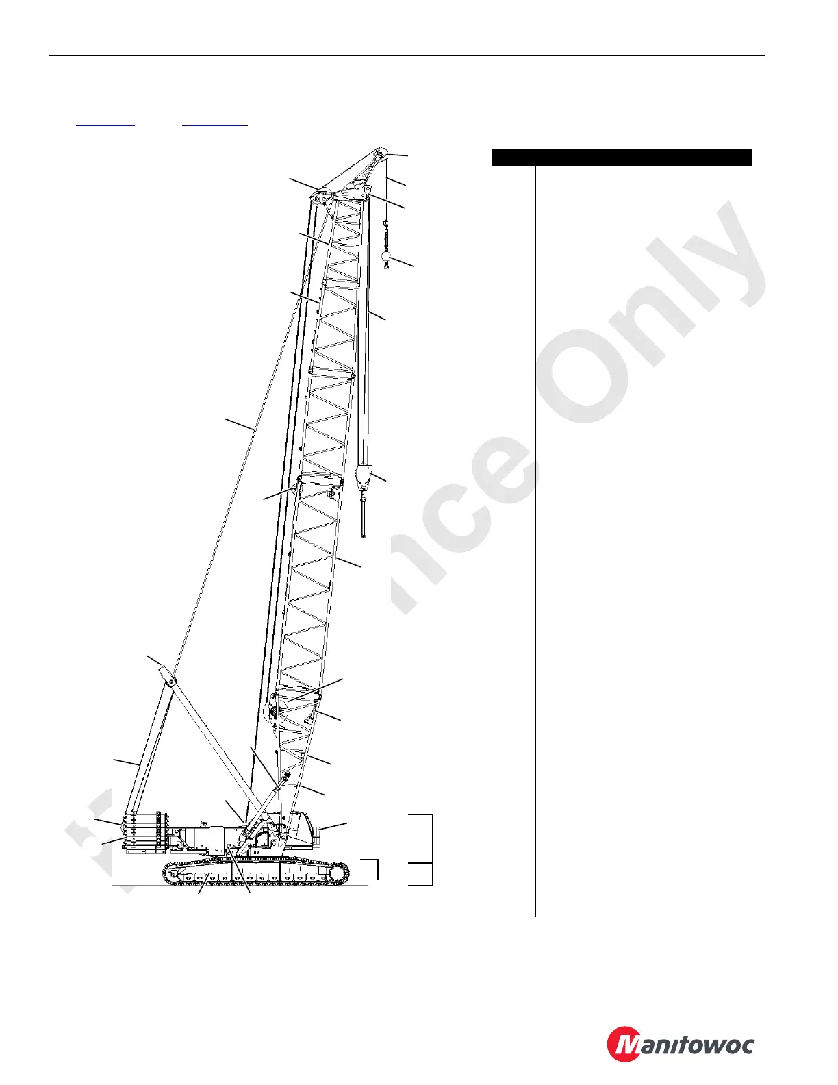
See Figure 1-1 through Figure 1-6 for component identification.
A10740-3
24
22
20
3
15
16
12
1
7
2
4
5
6
8
10
11
17
19
9
14
18
21
23
23
26
25
27
FIGURE 1-1
13
Item Description
1
Upperworks
2 Undercarriage
3 Operator Cab
4 Carbody Counterweight (both ends)
5 Enclosures (both sides)
6Crawler
7 Crane Counterweight
8 Boom Hoist Sheaves
9 Boom Hoist Wire Rope
10 Mast Arms with Cylinders
11 Mast (live)
12 Telescopic Boom Stop
13 Boom Butt
14 Boom Insert
15 Wire Rope Guides (in insert)
16 Boom Straps
17 Transition Insert
18 Boom Top
19 Wire Rope Guide
20 Upper Boom Point
21 Lower Boom Point
22 Weight Ball
23 Load Lines
24 Load Block
25 Load Drum 1
26 Auxiliary or Luffing Hoist
27 Rigging Winch
28 Swing Drive
29 Carbody Counterweights (both ends)
30 Platform with Step
31 Crawler Drive
32 Carbody
33 Adapter Frame (rotating bed)
34 Rotating Bed Jack (both sides front)
(not furnished with European option)
35 Rotating Bed
36 Rotating Bed Jack (both sides rear)
(not furnished with European option)
37 Boom/Mast Hoist (standard) OR
Boom Hoist (MAX-ER)
38 Fuel Tank
39 Radiator
40 Power Plant (with pump drive)
41 Pumps
42 Hydraulic Tank
43 Load Drum 2
44 Boom Hinge Pin (right side)
45 Carbody Jacks (European option)