Manitowoc Published 05-03-17, Control # 228-03 3-17
16000 SERVICE/MAINTENANCE MANUAL ELECTRIC SYSTEM
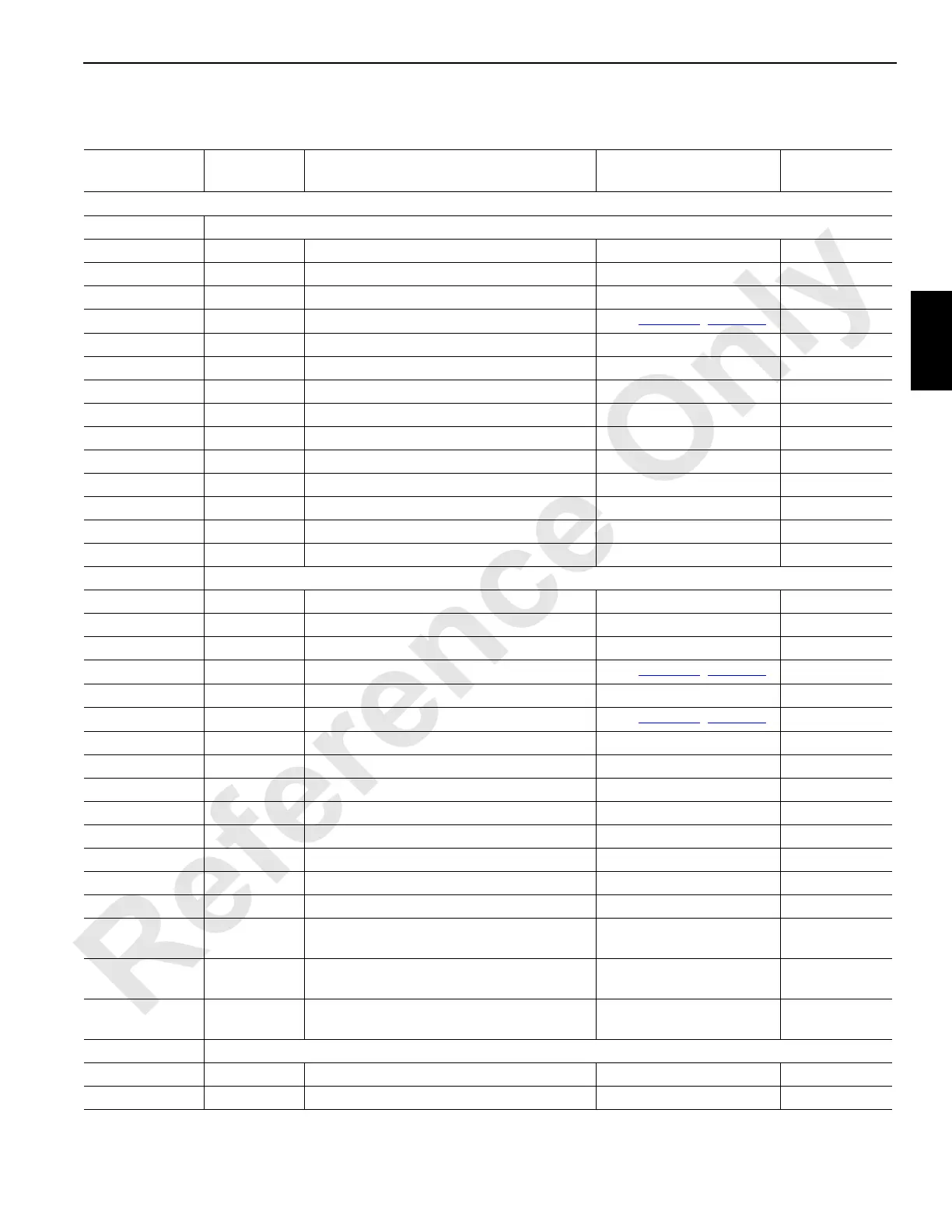
Node 6 — Drum Brakes, Pawls, and Motor Sensors
Reference Electrical Schematic A10871, Sheet 1, 10, and 16.
Connector #
Function
Type
Description Test Voltages
CAN Packet
Number
Input/output cable routing to remote nodes vary - see Electrical Schematic specific to your crane.
W63 Receptacle – Drum 3
W63-A Ground Load/Luffing (Drum 3) Brake Solenoid Ground N/A
W63-B DO-1 Load/Luffing (Drum 3) Brake Solenoid 0 Volts Off, 24 Volts On CAN26-1-1
W63-C Ground Load/Luffing (Drum 3) Right Motor Control Ground N/A
W63-D DO-2 Load/Luffing (Drum 3) Right Motor Control
See
Table 3-2, page 3-6
CAN26-1-2
W63-G Ground Load/Luffing (Drum 3) Pawl Solenoid - In Ground N/A
W63-H DO-4 Load/Luffing (Drum 3) Pawl Solenoid - In 0 Volts Off, 24 Volts On CAN26-1-8
W63-J Ground Load/Luffing (Drum 3) Pawl Solenoid - Out Ground N/A
W63-K NS-1 Node Select 1 Jumper to Ground 0 Volts (with Jumper) N/A
W63-L NS-2 Node Select 2 Jumper to Ground 0 Volts (with Jumper) N/A
W63-N Ground Load/Luffing (Drum 3) Minimum Bail Limit Ground N/A
W63-P DO-6 Load/Luffing (Drum 3) Minimum Bail Limit 0 Volts Off, 24 Volts On CAN26-1-32
W63-R DO-5 Load/Luffing (Drum 3) Pawl Solenoid - Out 0 Volts Off, 24 Volts On CAN26-1-16
W63-W DI-4 Load/Luffing (Drum 3) Minimum Bail Limit 0 Volts Off, 24 Volts On CAN47-1-8
W63-g Ground Jumper to Node Select 2 Ground N/A
W64 Receptacle – Drum 5
W64-A Ground Boom Hoist (Drum 5) Brake Solenoid Ground N/A
W64-B DO-11 Boom Hoist (Drum 5) Brake Solenoid 0 Volts Off, 24 Volts On CAN26-2-4
W64-C Ground Boom Hoist (Drum 5) Left Motor Control Ground N/A
W64-D DO-12 Boom Hoist (Drum 5) Left Motor Control
See
Table 3-2, page 3-6
CAN26-2-8
W64-E Ground Boom Hoist (Drum 5) Right Motor Control Ground N/A
W64-F DO-13 Boom Hoist (Drum 5) Right Motor Control
See
Table 3-2, page 3-6
CAN26-2-16
W64-G Ground Boom Hoist (Drum 5) Pawl Solenoid - In Ground N/A
W64-H DO-14 Boom Hoist (Drum 5) Pawl Solenoid - In 0 Volts Off, 24 Volts On CAN26-2-32
W64-J Ground Boom Hoist (Drum 5) Pawl Solenoid - Out Ground N/A
W64-R DO-15 Boom Hoist (Drum 5) Pawl Solenoid - Out 0 Volts Off, 24 Volts On CAN26-2-64
W64-g Ground Jumper to Node Select 1 Ground N/A
W64-h NS-1 Node Select 1 Jumper to Ground 0 Volts (with Jumper) N/A
W64-j NS-2 Node Select 2 Jumper to Ground 0 Volts (with Jumper) N/A
W64-n 24 Volts Load/Luffing (Drum 5) Motor Speed Sensor 24 Volts Nominal N/A
W64-p EC3A Load/Luffing (Drum 5) Motor Speed Sensor
1.2 or 3.2 Volts Not Moving,
2.2 Volts Moving
CAN47-6
2
W64-r Ground
Load/Luffing (Drum 3) Motor Speed Sensor/
Jumper to Node Select 2
Ground N/A
W64-s EC3B Load/Luffing (Drum 3) Motor Speed Sensor
1.2 or 3.2 Volts Not Moving,
2.2 Volts Moving
CAN47-6
2
W66 Receptacle – Drum 2 Controls
W66-A Ground Load Hoist (Drum 1) Brake Solenoid Ground N/A
W66-B DO-7 Load Hoist (Drum 1) Brake Solenoid 0 Volts Off, 24 Volts On CAN26-1-64