ELECTRIC SYSTEM 16000 SERVICE/MAINTENANCE MANUAL
3-38
Published 05-03-17, Control # 228-03
Counterweight Pin Status
Command state of the counterweight pin
cylinders, extended (shown) or retracted.
Boom Hinge Pin Status
Command state of the boom hinge pin
cylinders, extended (shown) or retracted.
Rotating Bed Pin Status
Command state of the rotating bed pins,
extended or retracted (shown).
Engine Cooling Fan Status
Command state of the engine cooling fan
(shown on).
Crane on Jacks Symbol
Image of the crane on jacks. The front view
icon is also shown on the Diagnostic screen.
Jack Status
Command state of a jack cylinder. The left rear
jack in the extended state is shown.
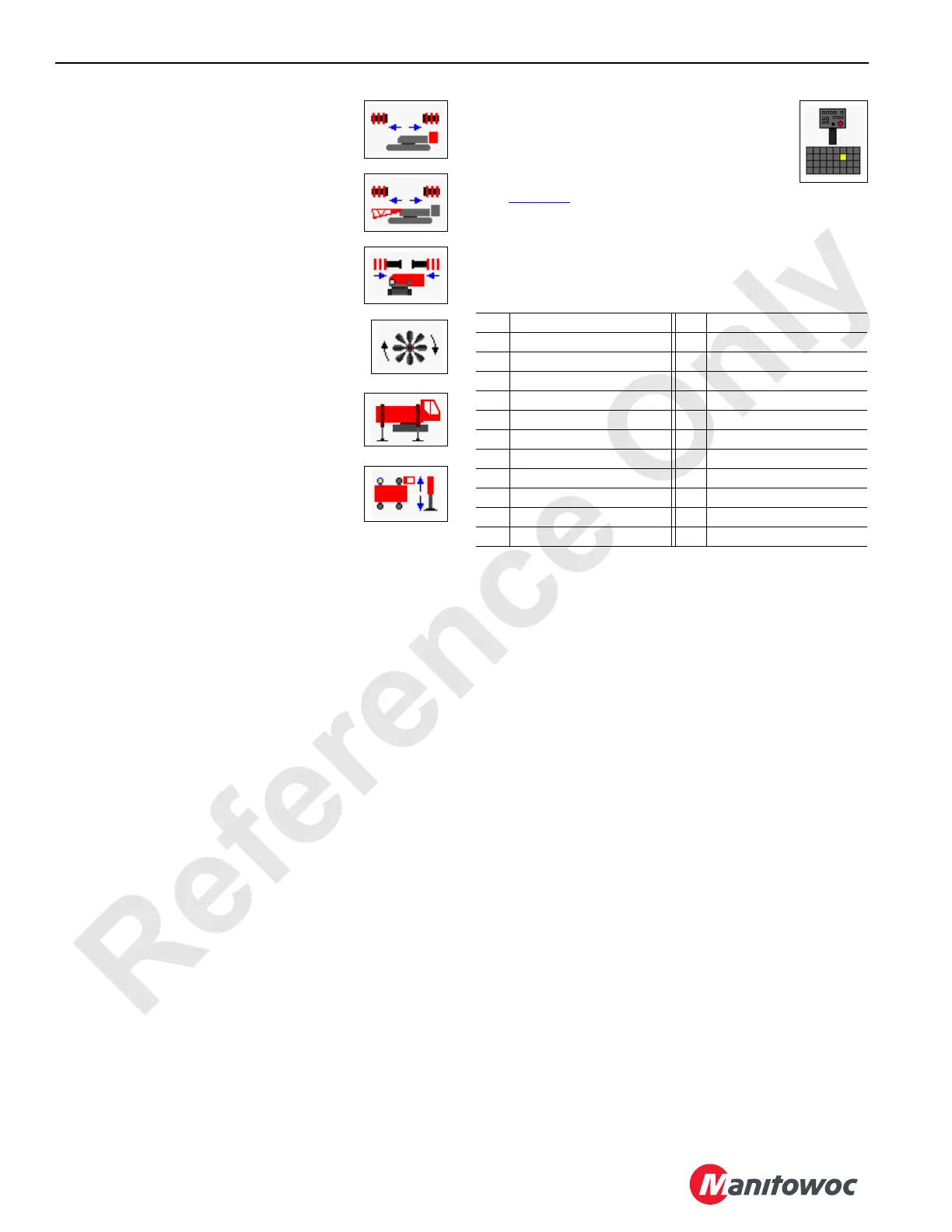
Remote Control: Wireless and Wired
Remote control status, indicating which switches
are closed.
Each control switch corresponds with a number
(see Table 3-9
). Switch numbers are 1 through 8
in row one, 9 through 16 in row two, 17 through 24 in row
three and 25 through 32 in row four. Not all switch numbers
are used. Switch number 14 (Left Front Jack - Extend) is
closed in the example shown.
Table 3-9 Wireless Remote Switch Identification
No. Description No. Description
1 Engine Low Speed 16 Right Front Jack - Extend
2 Engine High Speed 17 Left Rear Jack - Retract
7 Boom Pins - In 18 Left Rear Jack - Extend
8 Boom Pins - Out 19 Right Rear Jack - Retract
9 Front Adapter Pins - In 20 Right Rear Jack - Extend
10 Front Adapter Pins - Out 21 All Jacks - Retract
11 Rear Adapter Pins - In 22 All Jacks - Extend
12 Rear Adapter Pins - Out 24 Counterweight Pins - Out
13 Left Front Jack - Retract 25 Mast Lower
14 Left Front Jack - Extend 26 Mast Raise
15 Right Front Jack - Retract 27 Remote Stop