INTRODUCTION 16000 SERVICE/MAINTENANCE MANUAL
1-16
Published 05-03-17, Control # 228-03
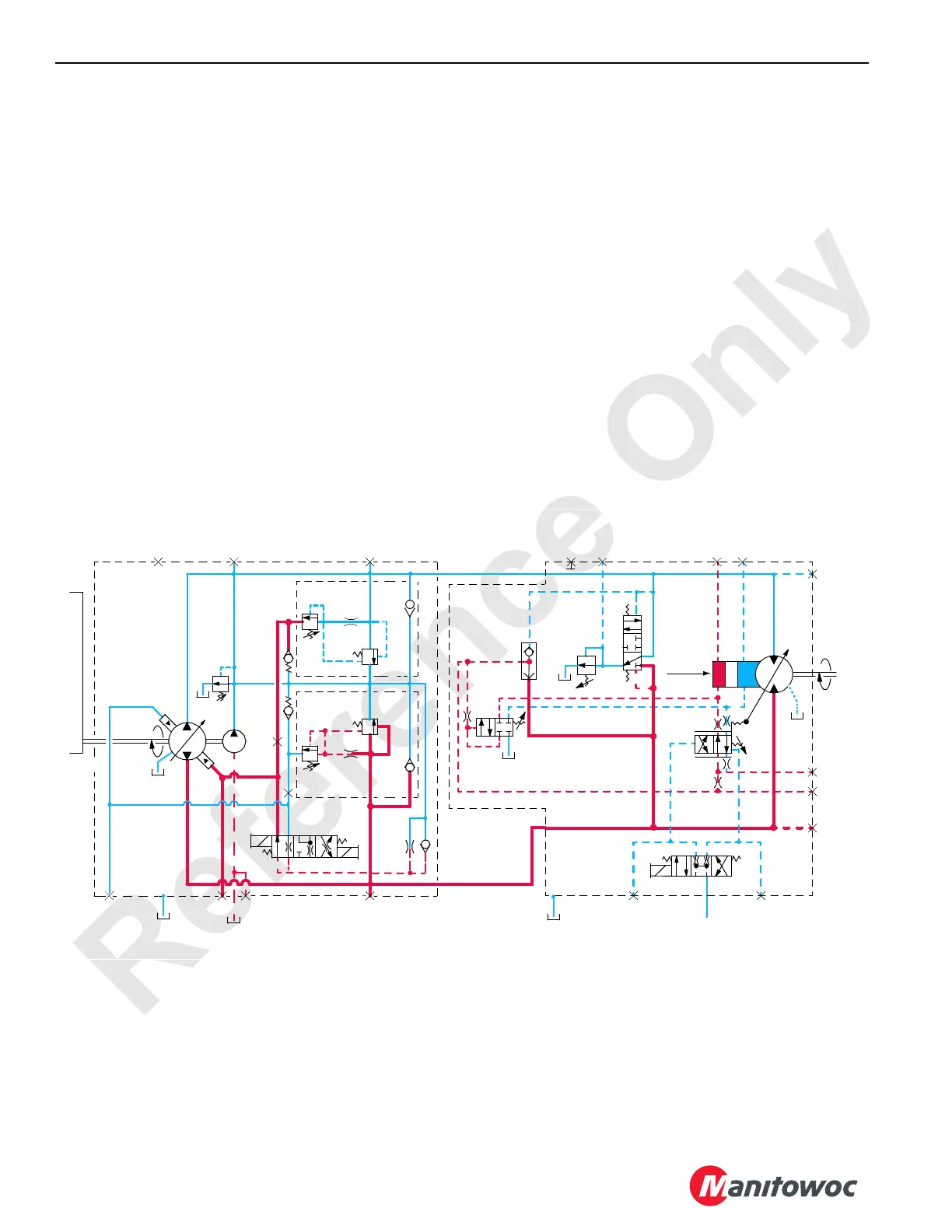
de-stroke the pump to limit system pressure. When rapid
loading produces pressure spikes, the system relief valve (5)
shifts. This allows high-pressure fluid to return to the tank
through the charge pump relief valve (6). Alternatively, fluid
transfers to the low-pressure side of the closed-loop system
through the charge flow make-up check valve (7).
In other system pumps, the pressure limiting is controlled
through the relief valve section of the multifunction valves
only. The flow control orifice (8) is removed from the pump
EDC. Servo check valves are removed from the pump and
the lines to the servo control cylinders are plugged. These
changes permit the pump to react quicker to control handle
commands.
The pressure-limiting relief valve (1) serves as the pilot valve
to open the system relief valve (5) when the desired relief
pressure setting is reached. For example, if a pressure
imbalance occurs on both sides of the flow restrictor (9), the
pressure-limiting valve opens and the system relief valve
relieves system pressure. Hydraulic fluid is directed to the
tank through the relief valve (7) or the flow is transferred to
the low-pressure side of the system through the make-up
check valve (8).
Pump displacement depends on the swashplate tilt angle.
The swashplate angle also affects pump speed.
Each variable-displacement motor, except travel, begins
operation at maximum displacement (high torque, low
speed) and shifts to minimum displacement (low torque, high
speed) if the torque requirement is low. The motor remains in
maximum displacement until the servo PC valve (10)
receives a command from the PCP valve (11) to direct the
system pressure and flow from the shuttle valve (12) to the
minimum displacement side of the servo cylinder (13) that
shifts the motor. As the PCP valve opens in proportion to the
output voltage received from the node controller, the pilot line
pressure is directed to shift the servo PC valve. After
overcoming the adjustable valve spring (14) and valve spring
(15), the servo PC valve shifts and directs fluid to stroke the
motor at minimum displacement output. If the load at the
motor shaft increases, the force on the adjustable valve
spring increases. This shifts the servo PC valve to de-stroke
the motor to maximum displacement for safe load handling.
The load drums and boom/mast hoist motors also have a
Pressure Compensating Over-Ride (PCOR) valve (16) that
is enabled when system pressure of 340 bar (4,931 psi) is
reached. When the system pressure exceeds the PCOR
setting, the valve shifts to direct flow from the shuttle valve
into the maximum displacement side of the servo cylinder.
The PCOR valve over-rides the command from the servo PC
valve, increasing motor displacement and output torque,
while reducing output speed. When the PCOR valve closes,
control of the motor returns to the servo PC valve.
The travel motor servo is the opposite of the other system
motors. The travel variable displacement motors begin
operation at minimum displacement (low torque, high
speed). The motor shifts to maximum displacement (high
torque, low speed) when the starting torque is required and
T1
T2
T3
3
8
1
2
14
5
16
7
9
11
12
10
15
18
17
13
6
4
FIGURE 1-9
Pump
Motor
Pump Drive
Input
350 psi
(24 bar)
A
D
C
Max.
Disp.
L2
M6
M4 M3
M1
M9
M5
M2
Output
G
M8E
B
M7
A
D
F
A
B
16-1003
 Loading...


