GROVE 6-55
TMS9000-2 OPERATOR MANUAL SET-UP AND INSTALLATION
Published 02-21-2019, Control # 611-05
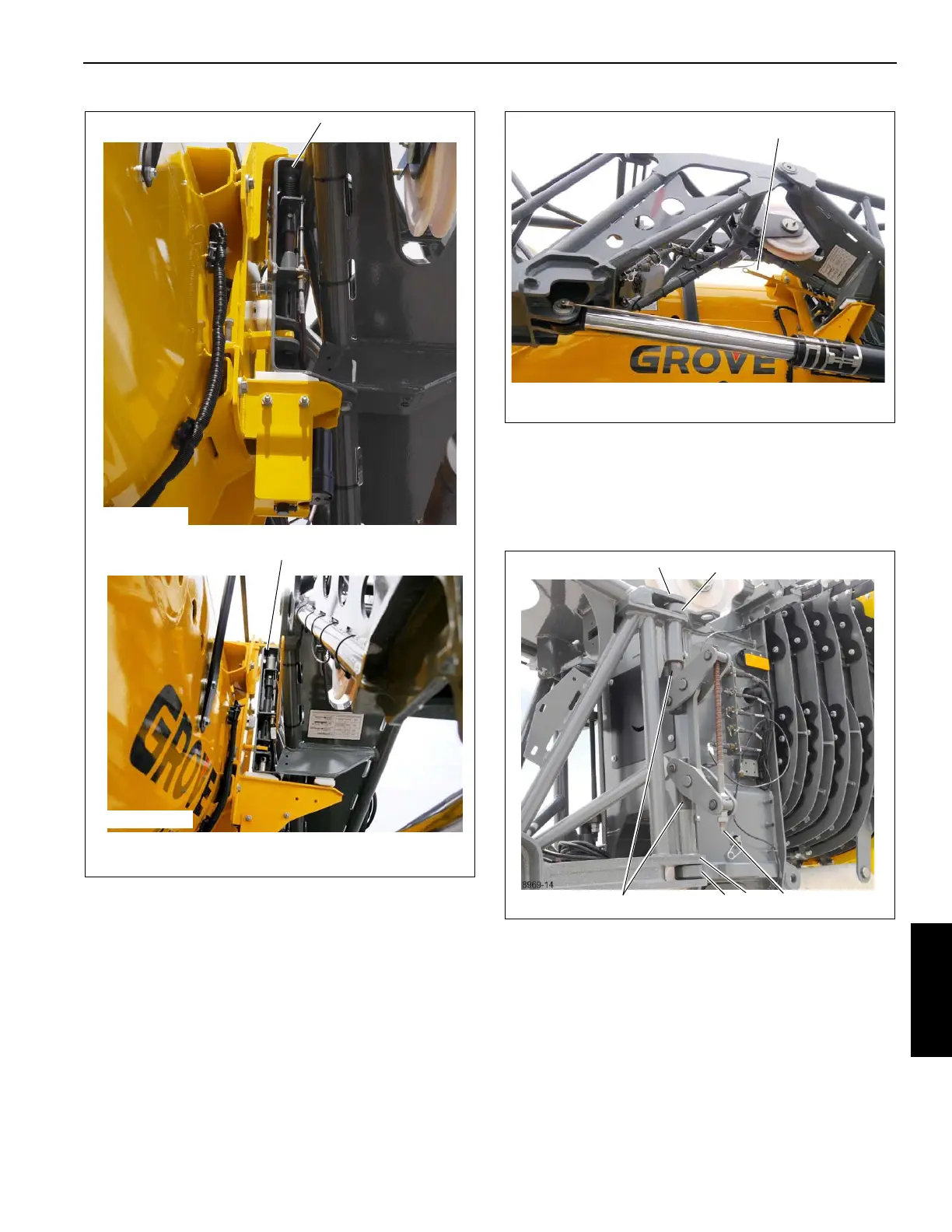
16. Swing the extension around to engage the base
extension anchor fittings (1, Figure 6-105) with the main
boom attachment fittings (2). Insert the pins (3) through
the fittings using an impact driver turning the jack screw
(4) counterclockwise. The jack screw drive bolt will
bottom out when the pins are fully engaged.
17. Attach the tag line to the nose of the fly extension.
Secure the tag line to the base extension (Figure 6-106).
FIGURE 6-103
8969-13
1
9728-13
Design B
Design A
1
FIGURE 6-105
8969-14
1
2
1 2
3
4
 Loading...


