SET-UP AND INSTALLATION TMS9000-2 OPERATOR MANUAL
6-54
Published 02-21-2019, Control # 611-05
10. Using the tag line swing the extension out to engage the
base extension anchor fittings (1, Figure 6-99) with the
main boom attachment fittings (2).
11. Install the pins (1, Figure 6-100) through the fittings
using an impact driver turning the jack screw (2)
counterclockwise. The jack screw drive bolt will bottom
out when the pins are fully engaged. The bolts and
washers (3) are at the end of the slots. Verify that the
pins are fully engaged and that the bolts and washers
are at the end of the slots.
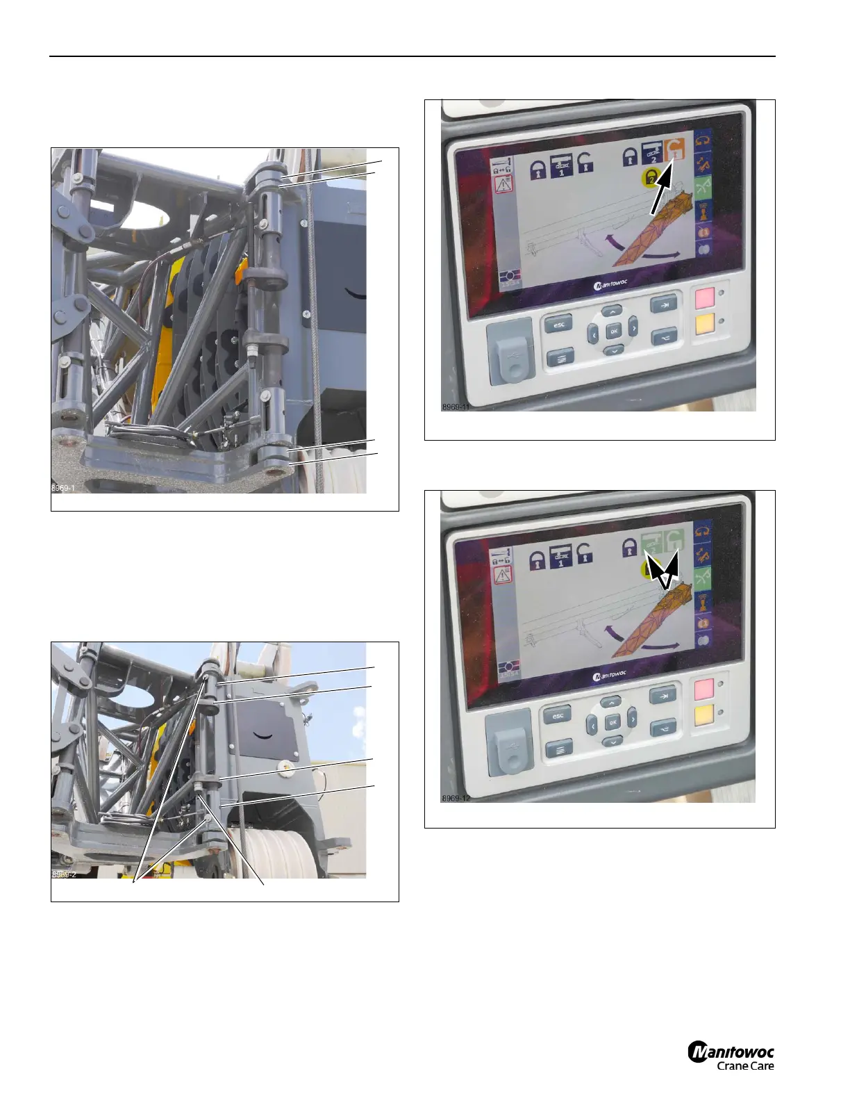
12. On the CCS display select pin #2, unlock (Figure 6-101).
13. The icons turn green, verifying pin #2 is unlocked
(Figure 6-102).
14. Verify pin #2 is unlocked (1, Figure 6-103). The handle
(1, Figure 6-104) should be in the down position.
NOTE: Pin #2 will not unlock unless the right side boom
nose pins are fully engaged. If Pin #2 does not
unlock make sure the right side boom nose pins
are fully engaged and the cable ends are inserted
through the pins, refer to (4, Figure 6-100).
15. Remove the cable retainer pin (1, Figure 6-108) from the
nose of the base extension and insert it into the holder.
 Loading...


