4.2 Instrument display
The MFT-X1 display is a 480 x 272 colour TFT screen, with a toughened and bonded glass screen.
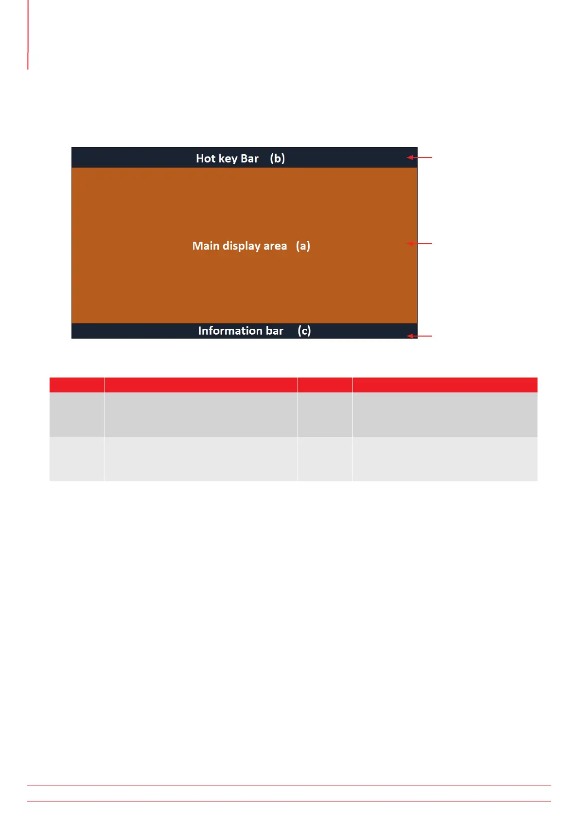
The display is divided into three areas:
3
1
2
Item Description Item Description
1 Hot key bar – Shows key functions 3 Information bar – shows secondary
data, time date, test mode, lead
connections and battery status
2 Main display area – shows all
measurement quantities and secondary
test information
The purpose of the main display area is to show the measurement results. The information shown in the main display
area and the way it is arranged depends on the test you are carrying out and is explained in the relevant sections for
each type of test.
The display uses colour coded background for different tests, as used by Megger Limited across instrument ranges
4.2.1 Colour coded backgrounds
So that you can see immediately which test you have selected, even from a distance, the background colour of the
main display area changes to match the test function colour code:
Dark grey – Voltage or Current
Orange – Continuity
Red – Insulation
Green – Loop impedance
Yellow – RCD testing
Brown – Earth testing
Blue – Result storage
Dark grey + cog – Setting
www.megger.com
MFT-X1
18
Instrument Controls