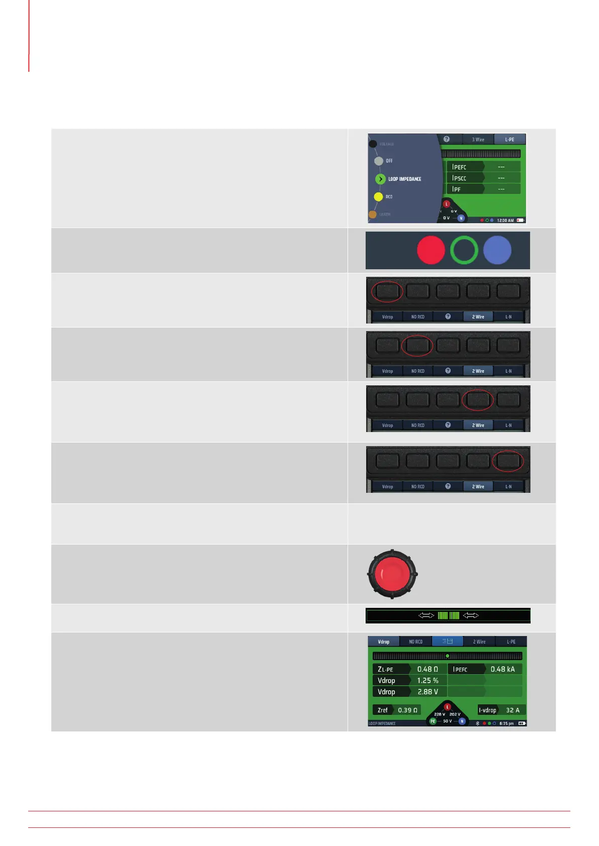
14.12.4 Making a Volt drop measurement
NOTE : This is a Phase to Neutral (L-N) or Phase to Phase (L-L) measurement.
You do NOT need to use the 3 wire measurement mode.
1. Turn the left-hand rotary knob to the Loop Impedance test
position (Z).
1.1. The display illuminates with a green background.
2. Plug your L (red) test-lead into the red socket, your N (blue)
test-lead into the blue socket.
3. Repeatedly press Hot key 1 to select Vdrop
3.1. Alternatively, press Hot key 1 once and use the right
hand rotary knob to select Vdrop
4. Repeatedly press Hot key 2 to select No RCD.
4.1. Alternatively, press Hot key 2 once and use the right
hand rotary knob to select No RCD
5. Repeatedly press Hot key 4 to select either 2 wire or 2 wire
HR.
5.1. Alternatively, press Hot key 4 once and use the right
hand rotary knob.
6. Repeatedly press Hot key 5 to select L-N. or L-L depending
on the circuit you are measuring.
6.1. Alternatively, press Hot key 5 once and use the right
hand rotary knob to select L-N or L-L.
7. Connect your test-leads to the L and N conductors at the
point on the circuit where you want to calculate the volt
drop.
8. Press and release the test button.
If AUTO START is enabled in settings press the test button
BEFORE connecting the test-leads.
9. The Confidence Meter™ bar reduces towards the middle as
the circuit is analyzed.
10. When the test is complete, the display shows the calculated
volt drop in volts and as a percentage of the supply voltage.
It will also display the Line to Neutral Loop Impedance (ZL-N) or
the Phase to Phase impedance (depending on Hot key 5 setting,
and the prospective short-circuit current, IPSSC.
www.megger.com
MFT-X1
76
Earth Loop Impedance testing – TrueLoop™