13.7 Ramp testing RCDs
NOTE : Separate ramp testing is not currently available for EV modes. A single ramp test can be isolated in
the AUTO sequence settings in SETUP by removing the 1/2 x I, 1 x I 2 x I and 5 x I options.
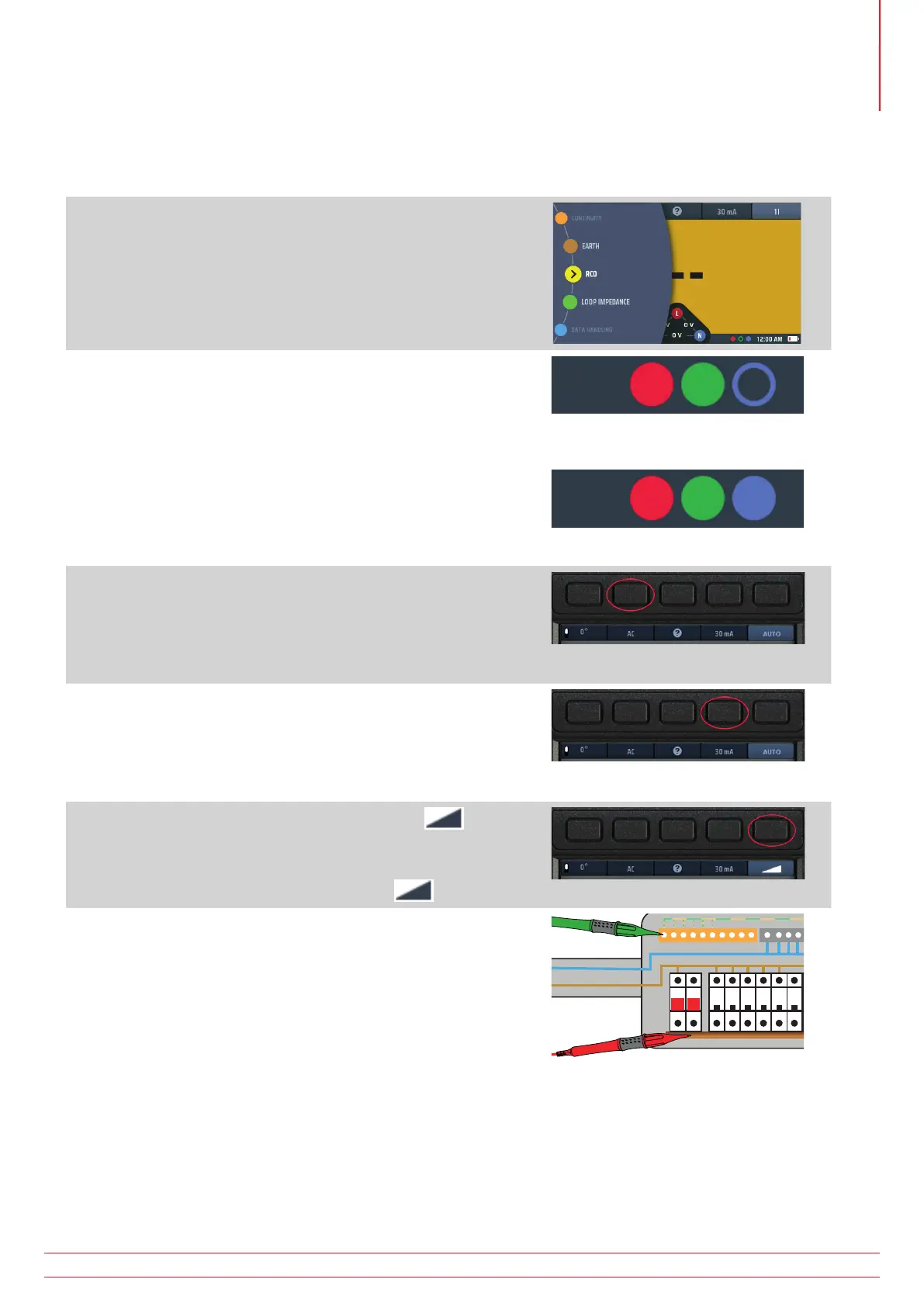
1. Turn the left-hand rotary knob to the RCD test position
(RCD).
The display illuminates with a yellow background.
2. For Type AC and A RCD you can use two-wire testing.
Plug your L (red) test-lead into the red socket and your PE
(green) test-lead into the green socket.
2.1. For type B and EV RCDs/RDCs you need three-wire
testing.
Plug your L (red) test-lead into the red socket, your
PE (green) test-lead into the green socket and your
N (blue) test-lead into the blue socket.
Three-wire is necessary for type B RCDs and EV/RDC.
or for type B or EV modes use 3 leads
3. Repeatedly press Hot key 2 until the type of RCD you are
testing is shown.
3.1. Alternatively, press Hot key 2 once and use the right-
hand rotary knob to select the type of RCD you are
testing.
4. Repeatedly press Hot key 4 until the current rating of the
RCD you are testing is shown.
4.1. Alternatively, press Hot key 4 once and use the right-
hand rotary knob to select the current rating of the
RCD you are testing.
5. Repeatedly press Hot key 5 until the ramp icon is
shown.
5.1. Alternatively, press Hot key 5 once and use the right-
hand rotary knob to select the ramp (
) option.
6. Connect your test-leads to the circuit on the load side of the
RCD you want to test.
Use a three-wire connection if you want the instrument to warn
you of reversed L and N.
NOTE : Connection can be made at the end of the circuit,
in the distribution board or on the RCD
NOTE : Some RCBOs will not trip if tested by connecting
directly onto the screw terminals of the RCBO.
www.megger.com MFT-X1
57
Residual current device (RCD) testing