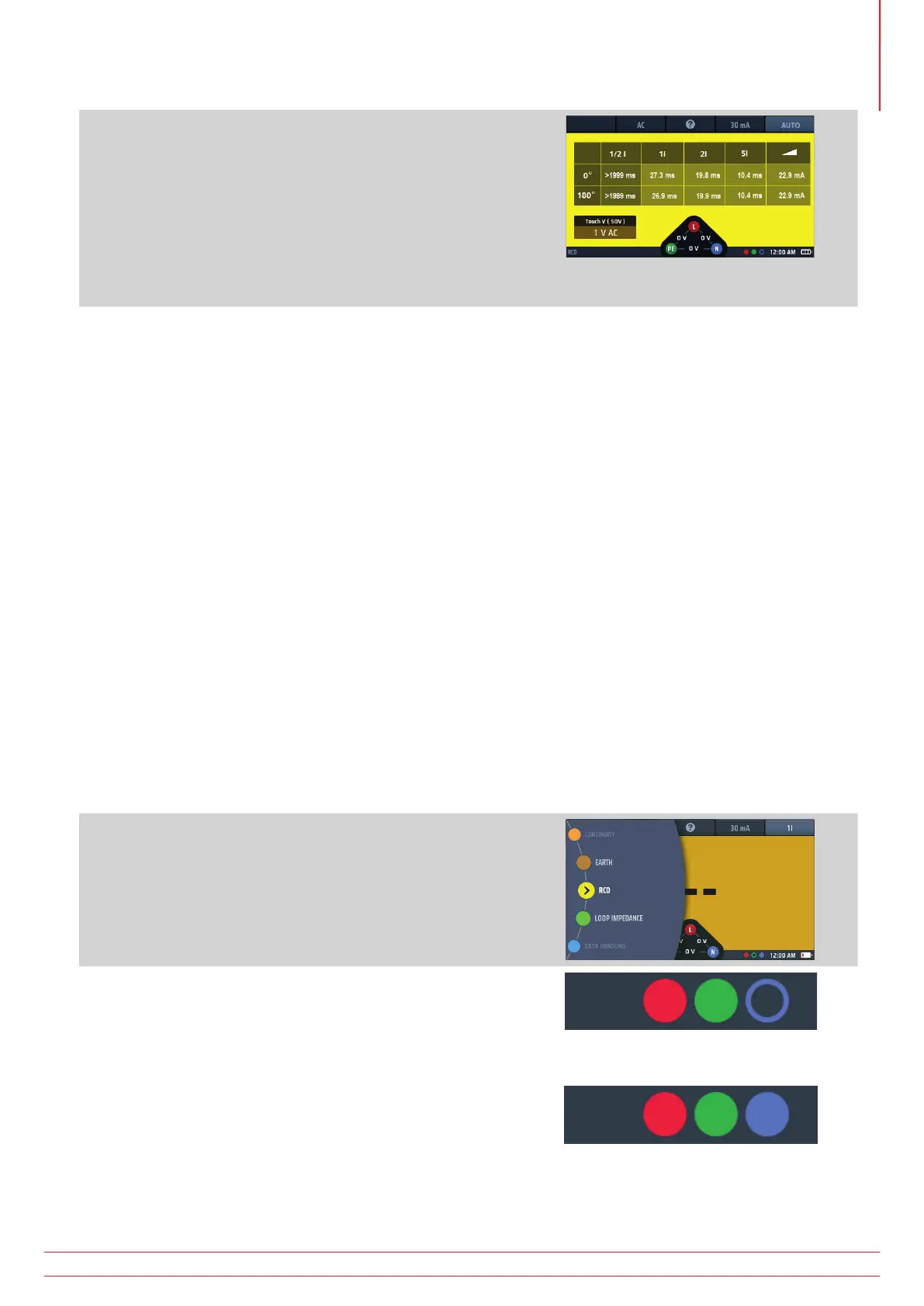
9. As each test in the sequence is completed, the result for that
test is added to the display. The testing progress is very clear
in the table of results.
10. When the whole test sequence is completed, the display
shows all the results.
11. The voltage widget at the base of the display will show OV
if the RCD was not reset after the final trip.
Resetting the RCD will show the supply voltage in the
voltage widget.
Fig 44: AUTO RCD test result progress
NOTE : Connection can be made at the end of the circuit, in the distribution board or on the RCD
NOTE : Some RCBOs will not trip if tested by connecting directly onto the screw terminals of the RCBO.
If the RCD does not trip the display shows:
>1999 ms (or >500 ms)* for the ½ x I test. This indicates the RCD has passed the test.
>300 ms for the 1 x I test. This indicates the RCD has failed the test by not tripping or tripping too late
>150 ms for the 2 x I test. This indicates the RCD has failed the test by not tripping or tripping too late
>40 ms for the 5 x I test. This indicates the RCD has failed the test by not tripping or tripping too late Note:
Connection can be made at the end of the circuit, in the distribution board or on the RCD
* >1999 ms or >500 ms options can be set in SETUP.
This value will depend on the standard to which the RCD is being tested
13.5.1 Customising the AUTO test sequence
The default AUTO test sequence is ½ x I, 1 x I, 2 x I, 5 x I and RAMP with all tests repeated at 0º and 180º. You can
customize the sequence in set up. You can remove any of the tests you don’t need in your AUTO sequence (if you
leave at least one test) and you can disable testing at 0º or 180º, but not both. For details of how to customize the
AUTO test sequence, Refer to 15.9.7 Auto sequence customisation on page 87..
13.6 RCD testing at a single current
1. Turn the left-hand rotary knob to the RCD test position
(RCD).
The display illuminates with a yellow background.
2. For Type AC and A RCDs you can use two-wire testing.
Plug your L (red) test-lead into the red socket and your PE
(green) test-lead into the green socket.
2.1. For type B and EV RCDs/RDCs you need three-wire
testing.
Plug your L (red) test-lead into the red socket, your
PE (green) test-lead into the green socket and your
N (blue) test-lead into the blue socket.
Three-wire is necessary for type B RCDs and EV/RDC.
or for type B or EV modes use 3 leads
www.megger.com MFT-X1
55
Residual current device (RCD) testing