6. Press and hold the test button.
The test voltage is turned on after a one second delay
(three seconds for 1,000 V tests).
The measured insulation resistance is displayed
continuously.
7. Keep the TEST button pressed until the value displayed is
stable.
The analogue arc also provides a continuous indication of
the measured insulation resistance.
The test voltage is turned off when you release the test
button.
8. After the test, do not disconnect the test-leads from the circuit or asset under test until the voltage shown
on the display has fallen to a safe value.
8.6 Insulation test with test lock
If the lock-on function has been disabled in set up, you will not be able to use this function. Refer to 15.7.2 Lock
button available on page 84.
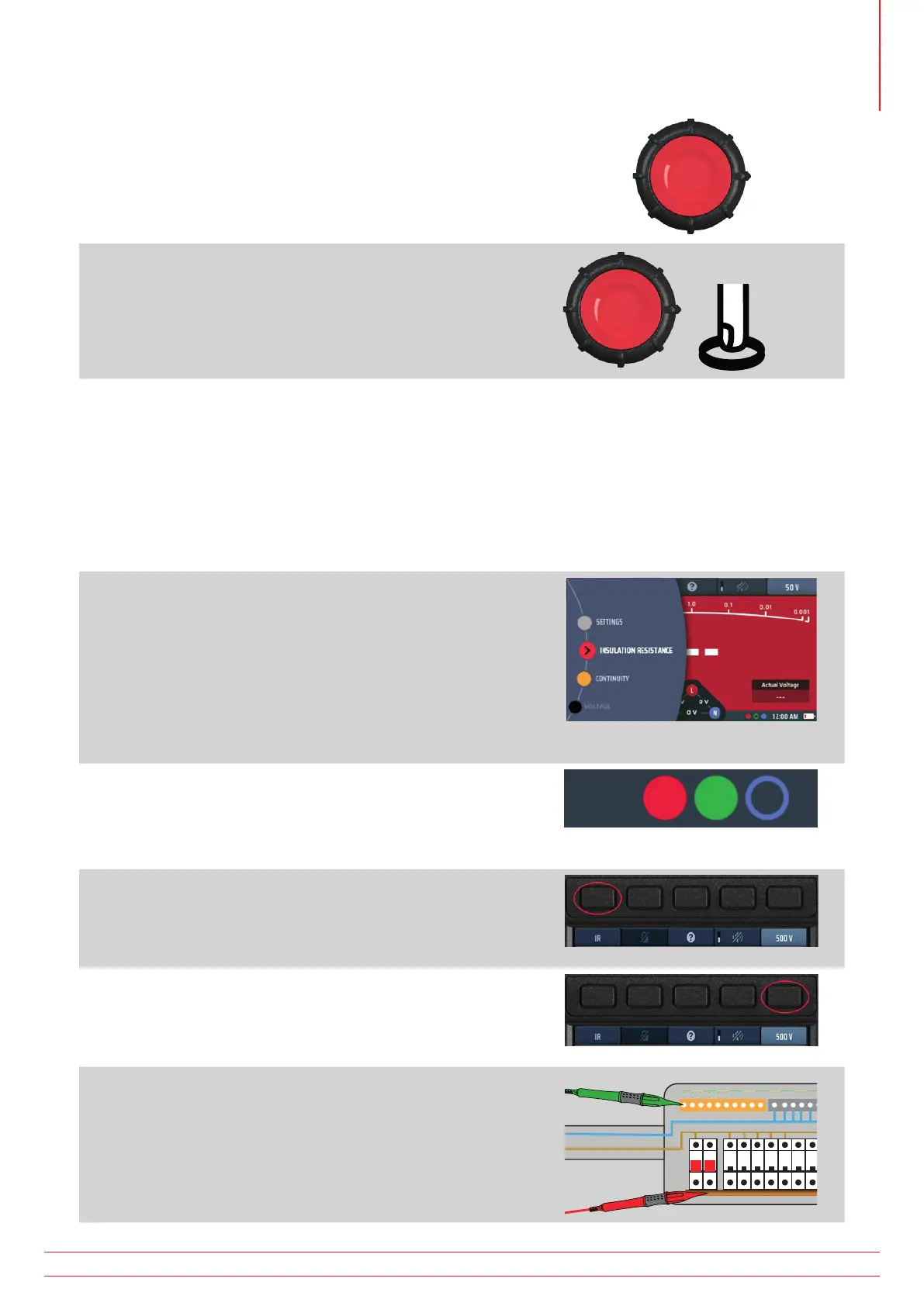
1. Turn the left-hand rotary knob to the insulation test
position (MΩ).
The display illuminates with a red background.
2. Plug your test-leads into the red and green sockets as
indicated in the INFO bar.
3. If necessary, repeatedly press Hot key 1 until the test type
shown below it is “IR”.
3.1. Alternatively, press Hot key 1 once and use the
right-hand rotary knob to select test type “IR”.
4. Press Hot key 5 until the test voltage you want is shown
below it.
4.1. Alternatively, press Hot key 5 once and use the
right-hand rotary knob to select the test voltage.
5. Connect your test-leads to the circuit or asset you want
to test.
www.megger.com MFT-X1
35
Insulation testing