11.6 Three-phase measurements
1. Turn the left-hand rotary knob to the Voltage position (V).
The display illuminates and has a black background.
2. Plug the test leads into the red (L1), green (L2) and blue (L3)
sockets.
3. Connect the red test-lead to the L1 conductor, the green
test-lead to the L2 conductor and the blue test-lead to the L3
conductor of the circuit to be measured.
You do not need to press the test button.
The test is running continuously and is constantly displaying the
voltages on the test terminals.
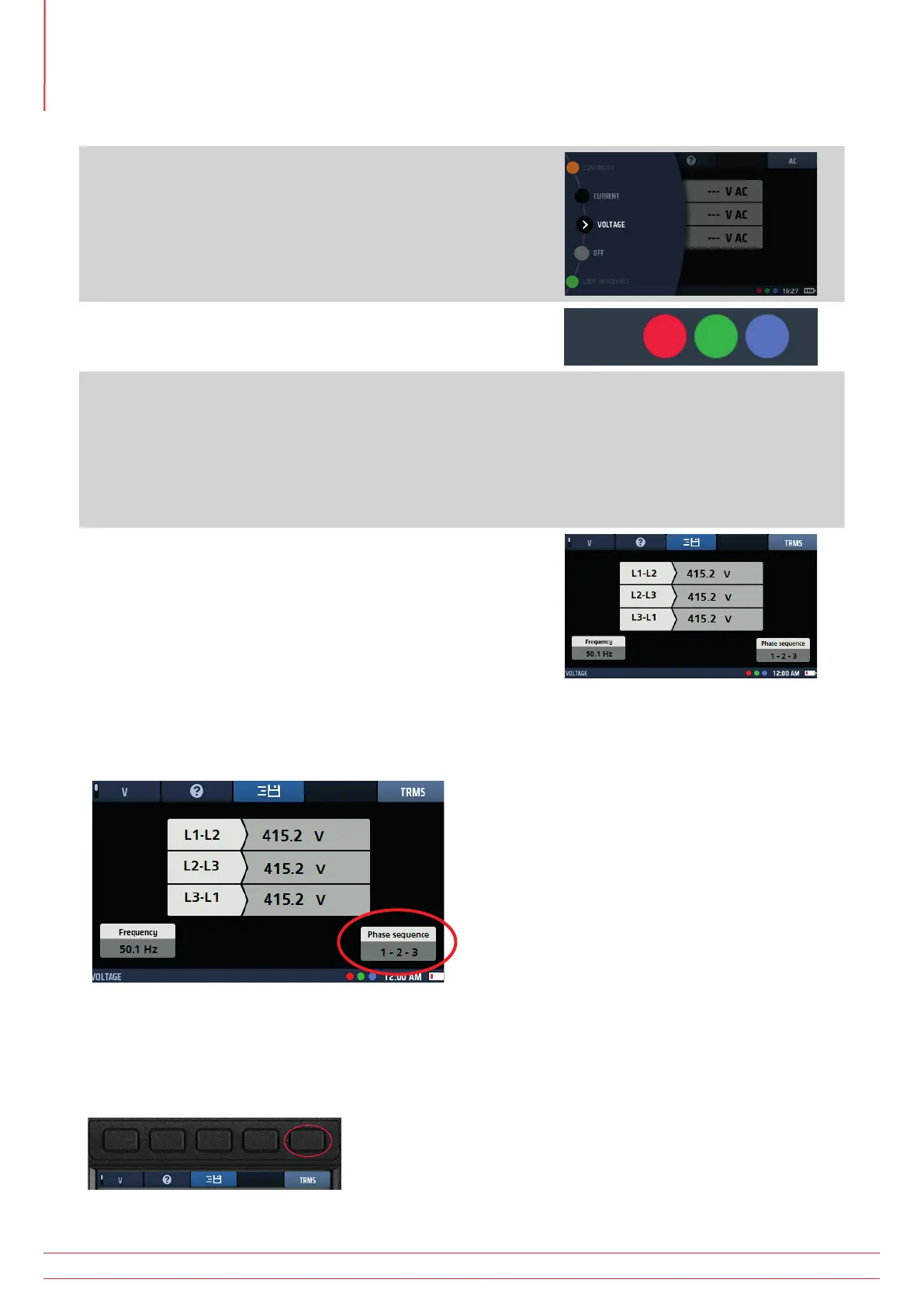
4. The instrument displays the L1-to-L2, L2-to-L3 and L1-to-L3
voltages simultaneously.
The instrument also displays the supply frequency.
The instrument also displays the phase sequence of the supply,
as below.
11.7 Phase sequence
When measuring three-phase voltages, the instrument automatically shows phase sequence.
Fig 34: Voltage phase rotation
Normal phase sequence is shown as 1-2-3. Reverse phase sequence is shown as 3-2-1.
If the instrument is set to DC mode and phase rotation is detected, it automatically switches to TRMS mode and the
display area below Hot key 5 flashes five times to alert the user.
Fig 35: Hot key 3
www.megger.com
MFT-X1
46
Voltage measurement