14.7 Measuring Loop Impedance (Zs) with RCD protection in circuit
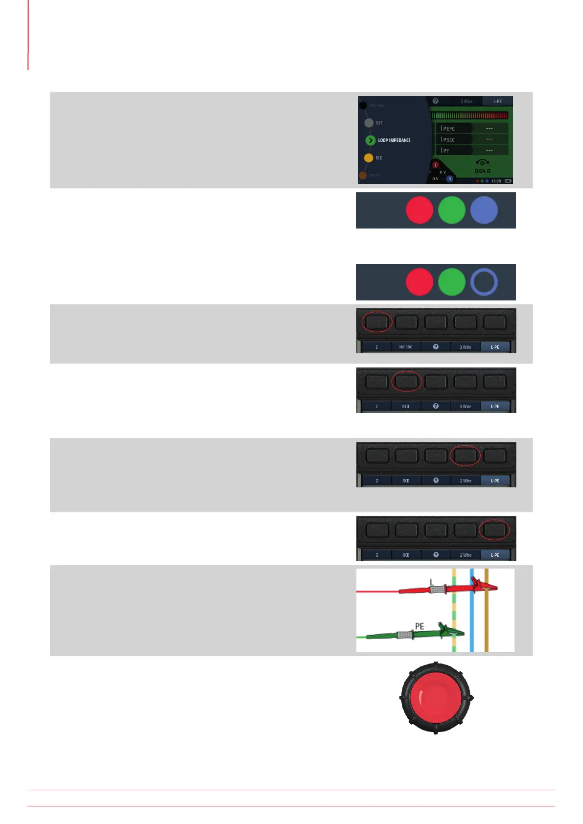
1. Turn the left-hand rotary knob to the Loop Impedance test
position (Z).
The display illuminates with a green background.
2. For a 3 wire test, plug your L test-lead into the red socket,
your PE test-lead into the green socket and your N test-lead
into the blue socket.
2.1. For a 2 wire test, plug your red (red) test-lead into the
red socket and your PE (green) test-lead into the green
socket.
or
3. Repeatedly press Hot key 1 to select impedance
measurement (Z).
3.1. Alternatively, press Hot key 1 once and use the right-
hand rotary knob to select impedance measurement (Z).
4. Repeatedly press Hot key 2 to select the type of RCD
protecting the circuit (RCD), either RCD or RDC EV.
4.1. Alternatively, press Hot key 2 once and use the right-
hand rotary knob to select the type of RCD protecting
the circuit, either RCD or RDC EV.
5. Repeatedly press Hot key 4 to select either 2 wire or 3 wire
testing. The example (right) uses 3 wire connection.
5.1. Alternatively, press Hot key 4 once and use the right-
hand rotary knob to select either 2 wire or 3 wire
testing.
6. Repeatedly press Hot key 5 to select L-PE.
6.1. Alternatively, press Hot key 5 once and use the right-
hand rotary knob to select L-PE.
7. Connect your test-leads to the L and PE conductors at the
point on the circuit where you want to measure the Loop
Impedance.
8. Press and release the test button
NOTE : If AUTO START is enabled in settings, press the test
button BEFORE connecting the test-leads. The test will
then start when it detects a live circuit on connection of
the leads, Refer to 15.8.3 AUTO test start on page 85.
www.megger.com
MFT-X1
68
Earth Loop Impedance testing – TrueLoop™