7.2 Continuity testing
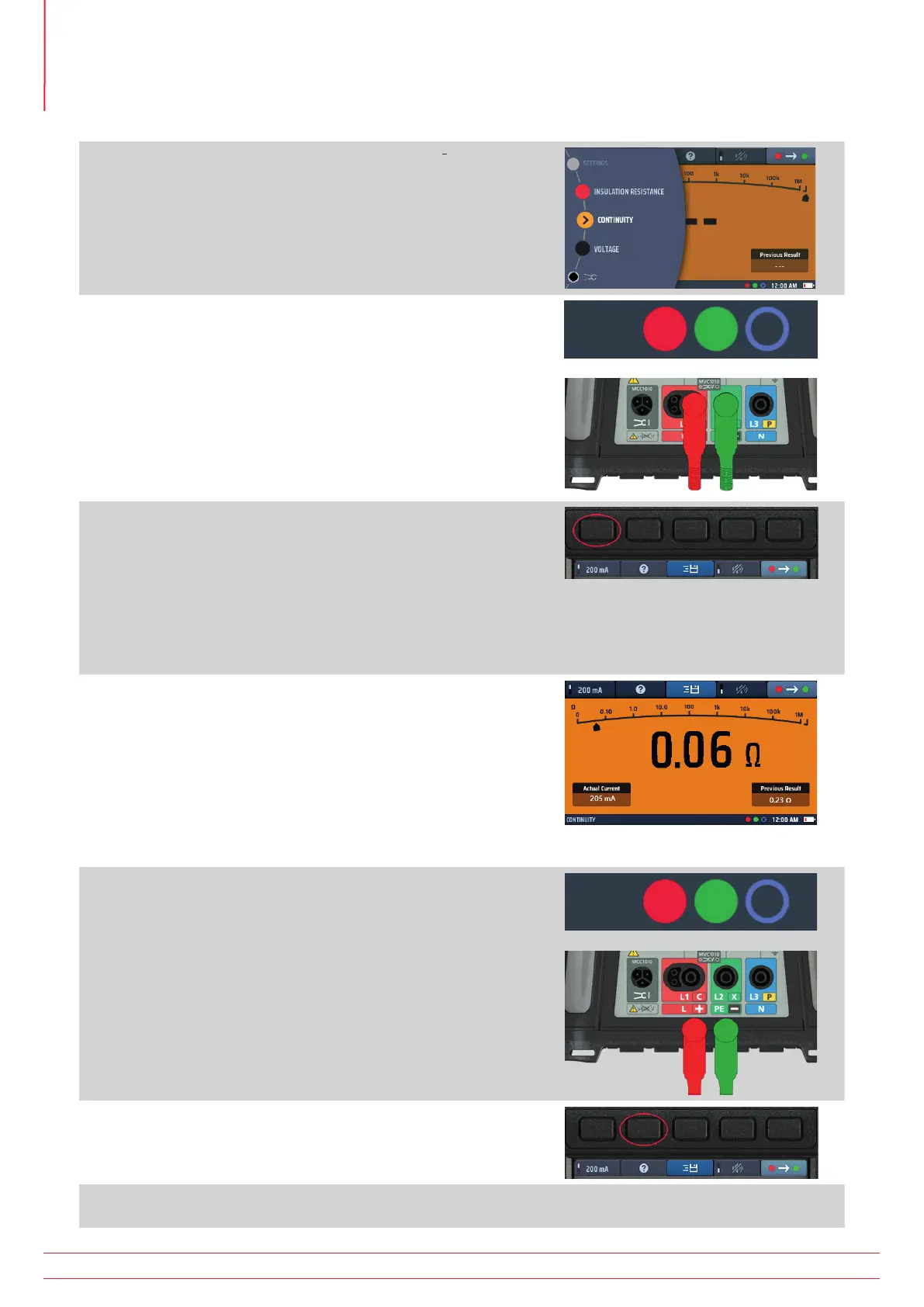
1. Turn the left-hand rotary knob to the Continuity position (Ω).
The display illuminates with an orange background.
2. Plug your test leads into the green and red sockets.
3. The default nominal test current is 200 mA. To change it to
10 mA, press Hot key 1. Press Hot key 1 again to revert to
200 mA.
The actual test current is shown at the bottom left of the
main display area.
You do not need to press the test button.
The test starts as soon as you connect your test leads to
the circuit you are testing.
4. When the value displayed is stable, the instrument will beep.
5. The instrument shows the circuit resistance in the main
display area.
The instrument also indicates the circuit resistance on the
analogue arc in the main display area.
Fig 14: Continuity general
6. At the end of the test, disconnect the test leads:
The pointer will return to > 999 kΩ.
The actual current used during the test will remain in the
lower left window.
The main displayed value will be transferred to the
previous results window in the lower right of the display.
This is to ensure that a subsequent measurement is
shown in the main display. If the first value was left
in the main display it could be mistaken for the next
measurement.
7. For help on connection of test leads to the circuit, press HELP
on Hot key 2
8. To save the result or send to a mobile device, Refer to 16. Download results to a remote device on
page 89.
www.megger.com
MFT-X1
28
Continuity testing and resistance measurement