VM600 networking manual MAVM600-NET/E 9 - 9
Edition 9 - February 2018
MPC4 card
SETTING UP A MODBUS CONNECTION (CPUM SW VERSION 071 OR LATER)
As can be seen from the analysis in Table 9-7, this line of the configuration file is used to
configure the channel 4 vibration data value of the AMC8 card located in slot 10 of the rack.
This parameter is available at the Modbus address 30003 as a 16-bit unsigned value by using
the Modbus function 04.
The parameter is a scaled value with a real-value range from −50.50 to 250.00. This
real-value range corresponds to the 16-bit unsigned (see 8.6.3 Analog values (registers))
value as follows:
The minimum FSD value of −50.50 is encoded as 0x0000 in the Modbus register
The maximum FSD value of 250 is encoded as 0xFFFF in the Modbus side.
As these are the minimum and maximum values, real-world values less than −50.50 will be
clipped to 0x0000 and values greater than 250 will be clipped to 0xFFFF.
NOTE: Unlike firmware version 067 or earlier, CPUM cards running firmware version 071
or later support non-symmetrical scaling values. That is, it is no longer necessary
for the magnitudes of the minimum FSD and the maximum FSD to be equal.
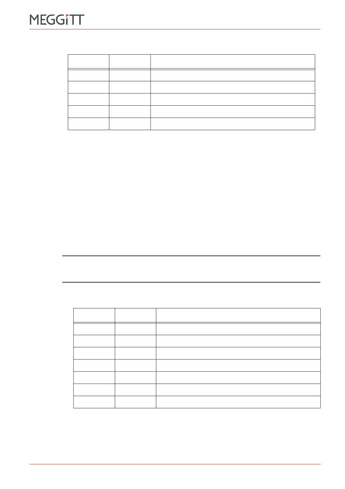
Table 9-8 illustrates reading the maximum channel scaling value using Modbus. The value is
coded as an F data type (and therefore only available as floating) so it requires two
consecutive 16-bit addresses. The values are available using Modbus function 04 at
addresses 30004 and 30005.
= Equals
10 SlotNr Slot number
AMC8 CardType Analogue Monitoring Card with 8 channels
C4 Channel
VData value
Table 9-8: Reading minimum and maximum values example – second line
Data Syntax Description
30004 Address Modbus address
4 Function Modbus function
F DataType Data type
= Equals
MAX
30003
4
Table 9-7: Reading minimum and maximum values example – first line (continued)
Data Syntax Description
 Loading...


