5-40 QX-830 Compact Industrial Scanner User’s Manual
Communication
Daisy Chain Autoconfigure
For quick setup of a daisy chain configuration.
The command to Autoconfigure the daisy chain is sent to the primary scanner and the
software responds in the following ways:
• Counts the number of secondary scanners in the daisy chain.
•
Assigns an internal ID number (1...n) to each secondary scanner, where the first secondary
scanner is number 1 (the primary scanner’s ID being a 0).
• Propagates the communication settings and the relevant operating modes of the primary
scanner to the ports of each secondary scanner.
• Resets each secondary scanner.
• Confirms that each secondary scanner has acquired the new settings.
When setting up a daisy chain operation, perform the following steps:
1. Set the primary scanner (the one connected to the host) to Serial Data Trigger Mode.
This sets all the scanners in the chain to Serial Data when the command is executed.
Important: All secondary scanners must be set to Serial Data Trigger Mode for Daisy
Chain to function.
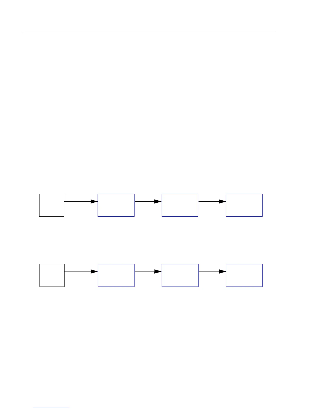
Before Autoconfigure, the primary scanner must be set to Serial (S):
2. Send the <K150DAISY> command from ESP’s Terminal.
3. If necessary, set the primary scanner to External Edge.
After
Autoconfigure
, the primary scanner can be set to
External Edge
(
E
), but the other
scanners must remain in
Serial
(
S
):
Important: If the scanner is Ethernet-enabled, first check to determine if RS-232 B is
available. If it is available, set RS-232 B as the Source port in Array Communication
Modes. Otherwise, set RS-232 A as the Source port. Port Routing for Symbol Data
Output and Extra Symbol Information will be disabled on the Source port.
Host
Primary
Scanner
Secondary
Scanner
Secondary
Scanner
SSS
Host
Primary
Scanner
Secondary
Scanner
Secondary
Scanner
ESS