3-4 QX-830 Compact Industrial Scanner User’s Manual
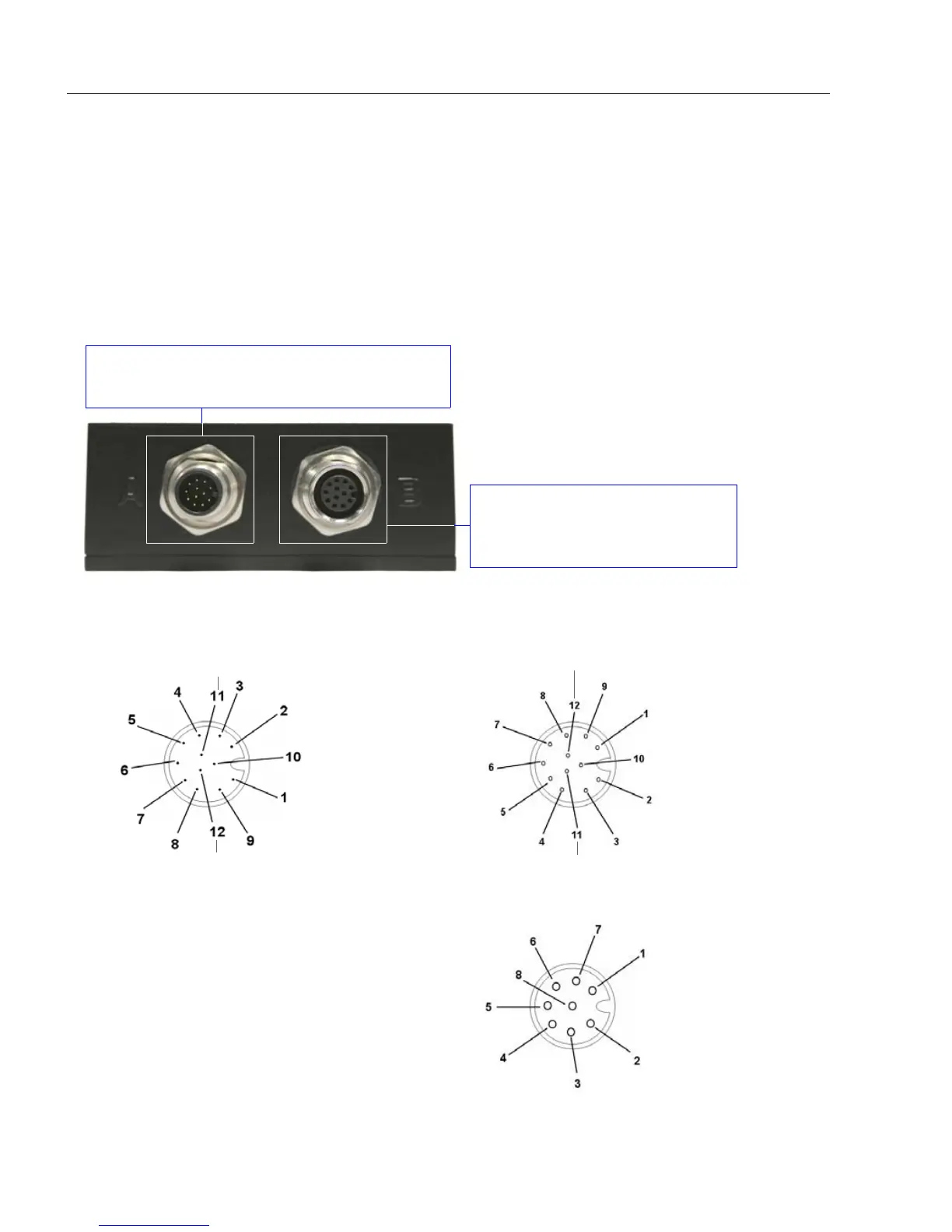
QX-830 and QX-1 Connectors and Pinouts
QX-830 and QX-1 Connectors and Pinouts
When deploying a network of scanners and interface devices in an industrial setting, it is
important to use components whose pin assignments are arranged in a way that avoids
communication errors and equipment damage. This can be achieved with components
that are designed in a logical, consistent, and easy-to-implement way.
The QX-830 has a very simple pin assignment methodology. The clearly identified connectors
at the back of the unit can be used to receive and bus power, and also to send and receive
data and commands.
QX-830 Connector Pin Assignments
Connector B is a 12-pin socket on
RS-232 scanner models, and an
8-pin socket on Ethernet models.
Connector A on the back of the QX-830 is a
12-pin plug on both Serial and Ethernet models.
QX-830 Connectors
Important: The 8-pin Ethernet
version of Connector B does
not have RS-422/485, Input 1,
or RTS/CTS pins.
Ground
Output 3
Output 1
Output 2
New Master
Default
Power
Input Common
Output Common
RS-232 RxD
Trigger
RS-232
TxD
Connector A (Serial) M12 12-pin Plug
Input
Common
RS-422/485 RxD (–)
RS-232 TxD/RS-232 RTS
Trigger
RS-232 RxD/RS-232 CTS
Power
Ground
RS-422/485
RxD (+)
RS-422/485
TxD (+)
RS-422/485 TxD (–)
Input 1
Termin ated
Connector B (Serial) M12 12-pin Socket
TX (+)
RX (–)
RX (+)
TX (–)
Termina ted
Term inated
Connector B (Ethernet) M12 8-pin Socket
Termin ated
Terminated