4-4 TM80 Telemetry Monitor Service Manual
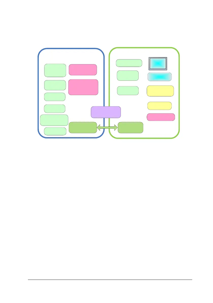
The figure below shows the software function deployment diagram:
Pace detection
Monitor battery
level
SpO2 module
communication
MPAN module
communication (NIBP
module)
Communicate with
the main control
board
MCU functional program
of parameter board
Detect nurse
calling key
ECG-ASIC
communication
(data sampling)
Detect power
on/off key
Speaker
control
Wi-Fi module control
Display
control
ECG algorithm
Touch screen
driving
Main control
transaction
management
Main control program
Detect menu key
Communicate
with M0+
UART
Three-color
indicator
control
Monitor
system voltage
Power switch controls
PMU management
4.2 System Signal Flow
The figure below shows the data flow of the TM80 Telemetry Monitor. The patients’
physiological data (ECG, SpO
2
and NIBP) monitored by the TM80 is transmitted
through the built-in low power consumption Wi-Fi module. The AP array picks up
wireless signal and forwards it to the CMS through the network system of the
hospital.

 Loading...