TM80 Telemetry Monitor Service Manual 2-5
2.4 Architecture of the TM80 Telemetry Monitoring System
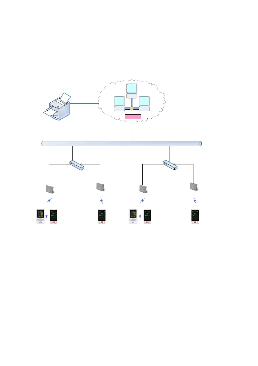
The following figure illustrates the physical units of the TM80 Telemetry Monitoring
System. It shows how these devices and functional units are interconnected to form
a complete telemetry monitoring system.
AP
AP
...
100
/1000
Mbps Switch
WLAN
802
.
11
a/
b
/g
/
n/
ac
...
Network
AP
AP
...
100
/
1000Mbps Switch
WLAN
802
.
11
a/
b
/
g
/
n
/
ac
...
...
CMS
The TM80 Telemetry Monitors are worn on patients. As shown in the figure above,
patients’ physiological information collected by the TM80 Telemetry Monitors is
transmitted through the low power consumption Wi-Fi modules built in the
telemetry monitors. Wireless signals are acquired by AP arrays and then are
transmitted to the CMS through the existing network system of the hospital. On the
CMS, the information is displayed, stored and processed based on a certain
algorithm and alarms are generated. In addition, patients can seek for help from
nurses on the CMS side by using the nurse call function. When a TM80 Telemetry
Monitor is connected to the CMS, doctors can view its patient information in the
ViewBed window of the CMS.

 Loading...