9-18 Structure and Assembly/Disassembly
9.3.6.11 Keyboard Top Cover Assembly
See Chapter 9.3.6, 9.3.6.2, and 9.3.6.10 for details.
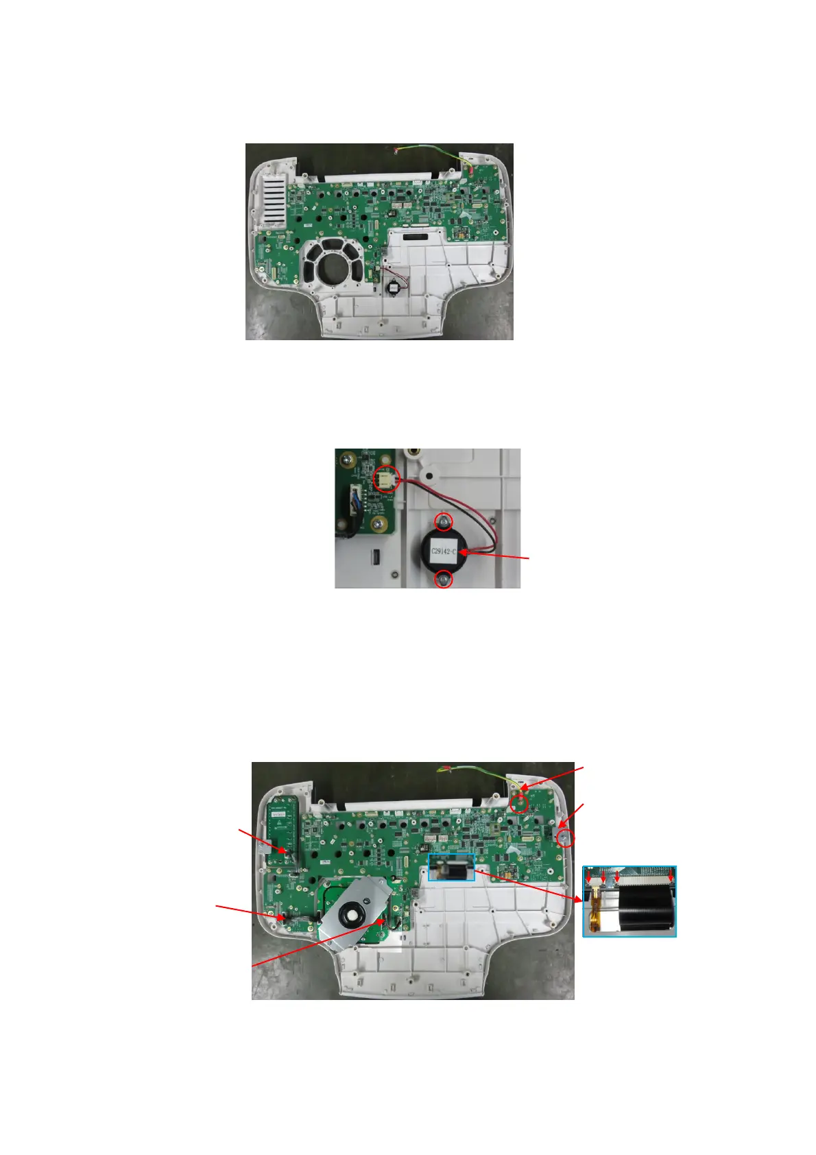
9.3.6.12 Buzzer
1. Refer to 9.3.6 Control Panel Assembly for details.
2. Unplug the connection wire of the buzzer. Unscrew 2 PT2.0X6 panhead tapping screws with
the screwdriver (M3, M4) to remove the buzzer.
9.3.6.13 The Control Panel PCBA
1. See Chapter 9.3.6, 9.3.6.6, 9.3.6.7 and 9.3.6.5 for details.
2. Wear the anti-electrostatic glove. Unplug the control wire (009-004567-00) of TGC board,
signal wire of the trackball (009-004569-00), signal control wire (009-004568-00). Push the clip
out towards the arrow’s direction to pull the cable. Unscrew 1 M3 X8 cross panhead screw and
1 M3 X 8 cross panhead screw with screwdriver from the grounding wire (009-004561-00) to
remove the grounding wire and the cap connection plate.
3. Unscrew 25 M3 X 8 cross panhead screws from the control panel PCBA with cross-headed
screwdriver (M3, M4) to remove the control panel PCBA (FRU).
Signal control cable of
trackball board
rounding wire
Signal control cable on
the TGC board
uzzer

 Loading...


