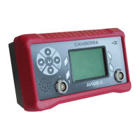
106491_C User manual AVIOR-2 MIP-2_En.docx
MIRION TECHNOLOGIES (Canberra) S.A.S, BP249, ZI de Vauzelles, 3760
20 NETWORK COMMUNICATION FUNCTION & DIGITAL I / O FOR AVIOR-2 I/O & MIP-2 I/O
Optionally an input / output connector (see § 7.1) to communicate the collected information over a
network.
This link mainly transmits the time stamped alarm, saturation and malfunction information in the form of
I/O digital signals and on a network link RS485 sends the values of the contamination measurement.
Other information is available such as connected probe type, background noise, device identification,
etc.
Refer to section 19.2 for details of the information available on the network link.
20.1 CONNECTORS PINOUT
RS485 connector and digital input / output
Description Signal Pin
DB25
ModBus RS485 - 20
ModBus RS485 + 8
ModBus VP 21
ModBus GND ModBus 7
Power ground GND +5/+24V 14
Power input 24VDC / 500 mA 1
Power output 5VDC / 150 mA 2
Digital input
GND Entrées TOR 12
Optocoupleur 1 25