187
CHAPTER 8 FUNCTIONS
8
8.8 Submaster Function
8.8.3 Example of communications using the submaster function
8.8.3 Example of communications using the submaster function
This section describes a procedure up to the system operation using the submaster function.
(1) System configuration
The following system configuration is used for explanation purpose.
(2) Link device assignment
Determine the link device assignment. 256 points are assigned to each station.
(a) RX/RY assignment
The setting for the link refresh target device of the local station is the same as that of the master station.
*1 Data that is sent from "Range of the station No.0 sending data" and stored in RY is stored.
Network No.1
Ethernet cable (1000BASE-T) Ethernet cable (1000BASE-T)
CPU module (Q10UDHCPU)
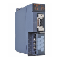
Master/local module (QJ71GF11-T2)
Input module (QX10)
Output module (QY10)
Master station
(station No.0)
Local station
(station No.1)
Submaster station
(station No.2)
Power supply module (Q62P)
X/Y00
to
X/Y1F
X/Y00
to
X/Y1F
X/Y00
to
X/Y1F
CPU module
1000
10FF
1100
11FF
1200
12FF
1000
10FF
1100
11FF
1200
12FF
X
Y
Station
No.0
Station
No.1
Station
No.2
Station
No.1
Station
No.0
Range of the
station No.2
sending data
Local station
RX
RY
Submaster station
RX
RY
Station
No.0
*1
Station
No.1
Station
No.2
Station
No.0
Station
No.1
Station
No.2
Station
No.2
Station
No.0
Station
No.0
Station
No.1
Master station
Station
No.1
Station
No.0
Station
No.2
Station
No.1
Station
No.0
Station
No.2
CPU module
X
1000
10FF
1100
11FF
1200
12FF
1200
12FF
0
FF
100
1FF
200
2FF
200
2FF
0
FF
100
1FF
200
2FF
0
FF
100
1FF
200
2FF
0
FF
100
1FF
200
2FF
0
FF
100
1FF
200
2FF
0
FF
100
1FF
1000
10FF
1100
11FF
RX
YRY
Range of the
station No.1
sending data
Range of the
station No.2
sending data
Range of the
station No.0
sending data
Range of the
sending data to
the station No.1
Range of the
sending data to
the station No.2
Range of the
station No.0
sending data
Range of the
sending data to
the station No.1
Range of the
sending data to
the station No.2
Area where data is sent to other stationsData sent from the master operating station
Data sent from slave stations

 Loading...


