33
CHAPTER 2 PART NAMES
2
For LED indication when the master/local module is in test mode, refer to the following.
( Page 64, Section 6.2, Page 71, Section 6.4.1)
2)
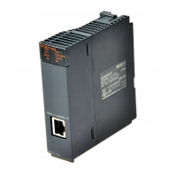
P1
PORT1 connector for CC-Link IE Field Network (RJ45 connector)
Connect an Ethernet cable. ( Page 68, Section 6.3)
There are no restrictions on the connection order of the cables for the "P1" connector and "P2" connector.
L ER
LED
ON
• The module has received abnormal data.
• The module is not performing loopback (only the master/local module whose serial number (first five
digits) is "12072" or later).
OFF
• The module has received normal data.
• The module does not perform loopback (only the master/local module whose serial number (first five
digits) is “12072” or later).
LINK
LED
ON Linkup in progress.
OFF Linkdown in progress.
P2
PORT2 connector for CC-Link IE Field Network (RJ45 connector)
Connect an Ethernet cable. ( Page 68, Section 6.3)
There are no restrictions on the connection order of the cables for the "P1" connector and "P2" connector.
L ER LED
(Same as the "P1" connector)
LINK LED
3)
Serial number display Displays the serial number printed on the rating plate.
No. Name Application

 Loading...