Chapter 5: Process Interfaces
55
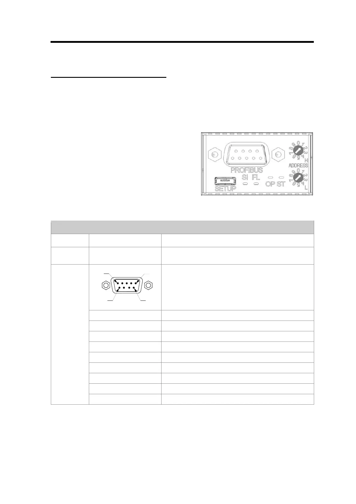
PROFIBUS Process Interface
Installation
Pinout
Figure 9 Profibus Connector
PROFIBUS Interface
Item Detail Description
SETUP - Mini USB connector, present for every interface variant.
Operates as MSD or CDC.
PIN 5
PIN 9
PIN 1
PIN 6
Standard D-Sub PROFIBUS connector
Pin-1 nc
Pin-2 nc
Pin-3 RXD/TXD - P
Pin-4 CNTR - P
Pin-5 DGND
Pin-6 VP
Pin-7 Nc
Pin-8 RXD/TXD – N
PROFIBUS
Pin-9 nc
Table 2 Profibus Interface
Power supply
The MF1 has to be powered via the Phönix MC-Series connector below the Zero switch. Therefore
a mating connector is included in the delivery. For the correct power supply specification see the
technical specification in Appendix A.