Chapter 5: Process Interfaces
87
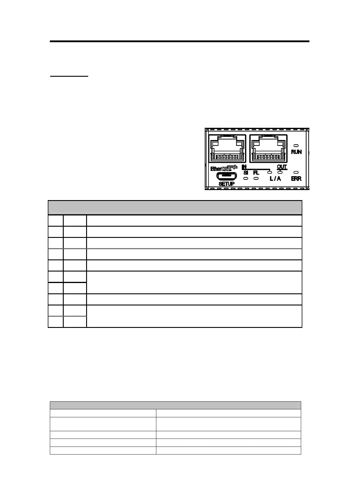
EtherCAT
Installation
Pinout
EtherCAT Pinout
Pin Signal Description
2 x RJ45
1 Tx+
2 Tx-
3 Rx+
4 -
5 -
Normally left unused; to ensure signal integrity, these pins are tied together and
terminated to PE via a filter circuit in the interface.
6 Rx-
7 -
8 -
Normally left unused; to ensure signal integrity, these pins are tied together and
terminated to PE via a filter circuit in the interface.
Power supply
The MF1 has to be powered via the Phönix MC-Series connector below the Zero switch. Therefore
a mating connector is included in the delivery. For the correct power supply specification see the
technical specification in Appendix A.
Cable
According to IEC 61784-5.
Example for cable type based on the template given in IEC 61918:2010
Characteristic CP 12/1, CP12/2 (EtherCAT) Type B cable
Nominal impedance of cable
(tolerance) 100 Ω ± 15 Ω (IEC 61156-5)
Balanced or unbalanced Balanced
DCR of conductors ≤ 115 Ω/km
Number of conductors 4